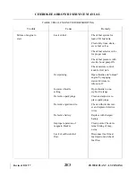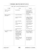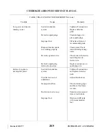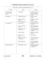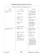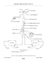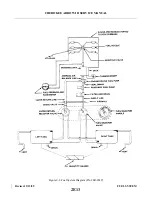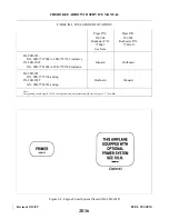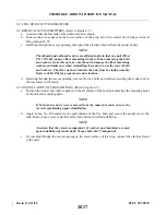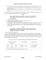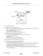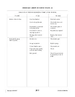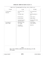
9-3. TROUBLESHOOTING. Troubles peculiar to the fuel system are listed in Table IX-III along with their
probable causes and suggested remedies. When troubleshooting, check from the power supply to the items
a ffected. If no trouble is found by this method, the trouble probably exists inside individual pieces of
equipment; they may be removed from the airplane and an identical unit or units, tested and known to be good,
installed in their place.
9-4. FUEL TANKS.
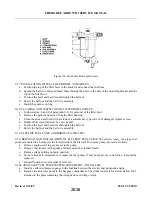
9-5. REMOVAL OF FUEL TANKS.
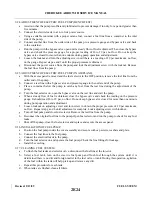
a. Drain the fuel from the fuel tank. (Refer to Draining Fuel System, Section II.)
b. Remove the screws from around the perimeter of the tank assembly.
c. Disconnect fuel line attached to tank. On PA-28R-201, disconnect vapor return line.
d. Pull the tank away from the wing assembly far enough to gain access for removal of the sender wires.
e. The tank is now free to be removed.
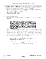
9-6. INSPECTION AND REPAIR OF FUEL TANK. If the fuel tank was previously sloshed, the entire interior
of the tank should be inspected for peeling of small areas of the sloshing compound. Indications are that in the
majority of cases, the peeling is started just inside the filler neck as a result of the metal nozzle of the gas filler
hose nicking the compound. The following items are recommended:
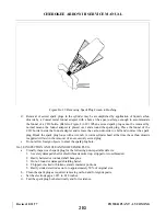
a. The entire interior of the main tanks should be inspected with the tanks drained. This is accomplished
with a mirror and inspection light through the filler neck. Small scrapes in the film adjacent to the
filler neck may be disregarded provided there is no indication of peeling.
b. If peeling has occurred and separated material is found, the fuel tank should be removed and resloshed
in accordance with the instructions included with each can of Randolph Sloshing Sealer, 802, Piper
part number 757 572V. (Approved under Mil. Spec. MIL-L-G0478.) One gallon of sloshing compound
is required per tank. After sloshing the tank, apply 1.5 lbs. air pressure and using a soap and water
solution, check for leaks.
c. After resloshing, reinspect as above at intervals of 100 hours. These inspections may be discontinued
after the second inspection if no peeling is discovered.
NOTE
The fuel tank should be replaced if the tank is damaged to the extend it
cannot be repaired by the above method.
9-7. INSTALLATION OF FUEL TANK
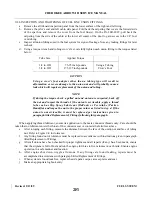
a. Slide the tank partly into position and connect the sender wires. On PA - 2 8 R - 2 0 1 T, connect vapor
return line.
b. Slide the tank completely into place and secure with screws around its perimeter.
c. Connect the fuel line.
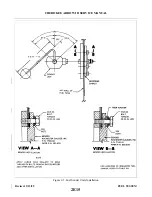
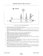
d. Fill the fuel tank and check for leaks, unrestricted fuel flow and proper sender indications on the
quantity gauge (refer to paragraph 9-11).
WARNING
Inspect aircraft for compliance with Piper Service Bulletin No. 625A, Fuel
and Vapor Return Lines Support. Failure to comply may lead to failure of
either line resulting in fuel leakage and possible engine failure.
Revised: 2/13/89
2E14
CHEROKEE ARROW III SERVICE MANUAL
FUEL SYSTEM
Summary of Contents for ARROW III
Page 4: ...THIS PAGE INTENTIONALLY LEFT BLANK 1A4...
Page 12: ...THIS PAGE INTENTIONALLY LEFT BLANK 1A12...
Page 94: ...Figure 4 2 Wing Installation Revised 2 13 89 1D22 CHEROKEE ARROW III SERVICE MANUAL STRUCTURES...
Page 171: ...lH3 INTENTIONALLY LEFT BLANK...
Page 172: ...lH4 INTENTIONALLY LEFT BLANK...
Page 286: ...THIS PAGE INTENTIONALLY LEFT BLANK Revised 2 13 89 2A8...
Page 528: ...INTENTIONALLY LEFT BLANK 2K10 THRU 2L24 2K10...

