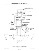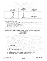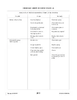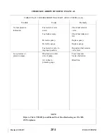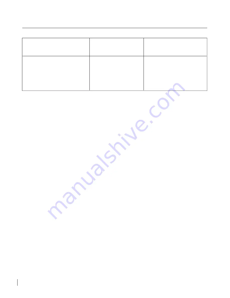
TABLE IX-III. TRANSMITTER/FUEL GAUGE TOLERANCES
Tolerance
Actual Fuel in
Gauge Reading
(Plus or Minus)
Tank (U. S. Gal)
(U.S. Gal)
(Needle-Widths)
Full
F
2
32.5
30
2
22.5
20
2
12.5
10
1
2.5
Zero
Plus 0 - Minus 1
0 Empty
Empty Dot
1/2
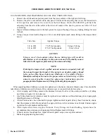
9-21. ELECTRIC FUEL PUMP. (WELDON) (PA-28R-201)
9-22. REMOVAL OF FUEL PUMP.
a. Remove the cowling by releasing the cowl fasteners and removing the screws around the nose gear
and across the aft edge of the cowl.
b. Ascertain the fuel shutoff is in the off position.
c. Disconnect the electrical leads from the pump.
d. Disconnect the fuel lines from the pump.
e. Remove the cap screws, washers and plate and remove the pump from the airplane.
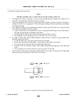
9-23. DISASSEMBLY, REPAIR AND ASSEMBLY OF FUEL PUMP. Overhaul of the fuel pump is not
recommended because of special tools needed. If overhaul is necessary, the pump should be returned to:
The Weldon Tool Company
3000 Woodhill Road
Cleveland, Ohio 44104
However, some repairs may be accomplished as follows:
a. Replacement of shaft seal.
1. Separate the pump end assembly from the motor by removing the four machine screws. Note the
relationship of the pump and motor before separation.
2. The shaft seal is assembled with a light press fit into the insert. It can be pried loose from the insert
without disassembly of the pump.
3. Check the shaft for burrs, scratches or any defects which might cause the seal to wear. Any defect
would be cause for pump replacement.
4. Position a new seal on the shaft and press into place.
5. Assemble the pump end assembly to the motor in the original position. Install the four machine
screws and safety.
b. Repair of the relief valve.
1. Remove the adjusting screw from the pump end assembly. Do not change the position of the jam
nut.
2. Remove the valve plunger and spring.
3. Inspect the valve seat, plunger and spring for condition and wear. If the valve seat is damaged, the
pump should be replaced.
4. Reassemble the plunger, spring, if installed, and adjusting screw to the pump.
5. Adjust the pump pressure as described in paragraph 9-24 or 9-25.
Revised: 2/13/89
2E23
CHEROKEE ARROW III SERVICE MANUAL
FUEL SYSTEM
Summary of Contents for ARROW III
Page 4: ...THIS PAGE INTENTIONALLY LEFT BLANK 1A4...
Page 12: ...THIS PAGE INTENTIONALLY LEFT BLANK 1A12...
Page 94: ...Figure 4 2 Wing Installation Revised 2 13 89 1D22 CHEROKEE ARROW III SERVICE MANUAL STRUCTURES...
Page 171: ...lH3 INTENTIONALLY LEFT BLANK...
Page 172: ...lH4 INTENTIONALLY LEFT BLANK...
Page 286: ...THIS PAGE INTENTIONALLY LEFT BLANK Revised 2 13 89 2A8...
Page 528: ...INTENTIONALLY LEFT BLANK 2K10 THRU 2L24 2K10...

