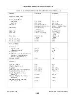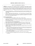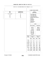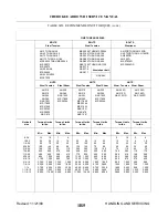
2-33. SERVICING HYDRAULIC PUMP/RESERVOIR. The fluid level of the reservoir of the combination
pump and reservoir should be checked every 50 hours by viewing the fluid through the filler plug hole in the
hydraulic pump. Access to the pump is through the panel at the right rear side of the baggage compartment.
To check fluid level, remove the filler plug located on the forward side of the pump and ascertain that fluid
is visible up to the bottom of the filler plug hole. Should fluid be below the hole, add fluid, MIL-H-5606A,
through the filler hole until full. Reinstall the filler plug and tighten.
NOTE
A small vent hole is located under the vent screw head. Retain 1/64 inch
clearance between the screw head and the small vent hole.
2-34. LANDING GEAR SYSTEM.
2-35. SERVICING LANDING GEAR. The landing gear consists of tires, brakes and oleo strut assemblies
These should be inspected for proper gear extension, scored piston tubes, possible hydraulic fluid leakage and
security and condition of all connection points. Check the brake linings for wear and frayed edges, and brake
discs for scoring. Replace if found necessary. Checked for proper adjustment of downlock hooks looseness of
drag links and side brace links. Minor servicing is described in the following paragraphs, and for detailed
service and overhaul instructions refer to Section VII.
2-36. OLEO STRUTS.
2-37. SERVICING OLEO STRUTS. The air-oil type oleo strut should be maintained at proper strut tube
exposures for best oleo action. The nose gear strut must have approximately 2.75 inches of piston tube
exposed, while the main gear strut requires approximately 2.0 inches of tube exposure. These measurements
are taken with the airplane sitting on level surface under normal static load. (Empty weight of airplane plus full
fuel and oil.) If the strut has less tube exposure than prescribed, determine whether if needs air or oil by
rocking the airplane. If the oleo strut oscillated with short strokes (approximately one inch) and the airplane
settles to its normal position within one or two cycles after the rocking force is removed, the oleo strut requires
inflating. Check the valve core and filler plug for air leaks, correct if required, and add air as described in
Paragraph 2-39. If the oleo strut oscillates with long strokes (approximately three inches) and the airplane
continues to oscillate after the rocking force is removed, the oleo struts require fluid. Check the oleo for
indications of oil leaks, correct if required and add fluid as described in Paragraph 2-38. For repair procedures
of the landing gear and/or oleo struts, refer to Section VII.
WARNING
Do not release air by removing the strut valve core or filler plug. Depress
the valve core pin until strut chamber pressure has diminished.
CAUTION
Dirt and foreign particles form around the filler plugs of the landing gear
struts, therefore, before attempting to remove these plugs, the tops of the
struts should be cleaned with compressed air and/or with a dry solvent.
Revised: 8/31/77
1B16
*CHEROKEE ARROW III SERVICE MANUAL
HANDLING AND SERVICING
Summary of Contents for ARROW III
Page 4: ...THIS PAGE INTENTIONALLY LEFT BLANK 1A4...
Page 12: ...THIS PAGE INTENTIONALLY LEFT BLANK 1A12...
Page 94: ...Figure 4 2 Wing Installation Revised 2 13 89 1D22 CHEROKEE ARROW III SERVICE MANUAL STRUCTURES...
Page 171: ...lH3 INTENTIONALLY LEFT BLANK...
Page 172: ...lH4 INTENTIONALLY LEFT BLANK...
Page 286: ...THIS PAGE INTENTIONALLY LEFT BLANK Revised 2 13 89 2A8...
Page 528: ...INTENTIONALLY LEFT BLANK 2K10 THRU 2L24 2K10...

