CAUTION
The central filter combined with a differential vacuum gauge will give a
decline in panel gauge indication when filter is clogged and vacuum
declines below recommended adjustment settings. Filters should be replaced
when gauge indication declines below the recommended adjustment setting;
do not readjust the regulator because accurate adjustment can only be
obtained with clean system filters.
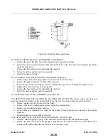
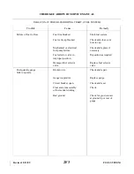
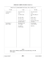
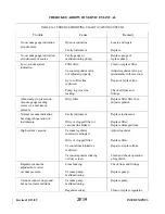
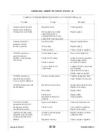
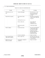
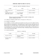
10-8. VACUUM REGULATOR. (Refer to Table 10-1 for Troubleshooting Instructions.)
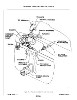
The vacuum regulator is mounted up under the instrument panel for easy maintenance access.
CAUTION
If the gauge is found to be accurate, all filters clean, and the vacuum gauge
still does not indicate within 4.8 to 5.2 inches of mercury range, the
regulator valve must be replaced.
a.
Symptoms that indicate regulator replacement are:
1. Rapid fluctuation of the vacuum gauge indication pointer.
2. Audible sound or chatter with fluctuation indication.
3. Non-repeatability of vacuum gauge indication when gauge is not suspect.
NOTE
Regulator malfunctions tend to increase vacuum power to the gyro
instruments. Although this excess of vacuum is applied, a loss of vacuum
does occur. Gyro instruments themselves act as limiting devices to keep
vacuum power from exceeding safe limits.
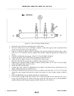
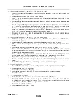
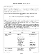
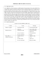
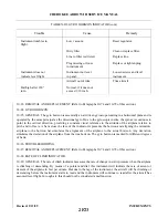
10-9. ENGINE DRIVEN VACUUM PUMP. (Refer to Table 10-1 for Troubleshooting Tips,) The engine driven
vacuum is a dry rotary vane positive displacement type, located on the rear accessory section of the engine. It
consists of an aluminum housing that contains a tempered sleeve in which an offset rotor is incorporated. The
assembly is driven by a series of engine driven gears mated to a coupling on the pump
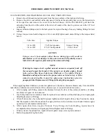
10-10. REMOVAL OF ENGINE DRIVEN VACUUM PUMP.
a.
Remove top engine cowling. (Refer to Chapter 71.)
b. Loosen hose clamp and remove hose from pump fitting.
c.
Remove the four retainer nuts, lockwashers, plain washers that secure the pump to the accessory
section of the engine.
d. Remove the pump, plug the open hose and cap the open pump line.
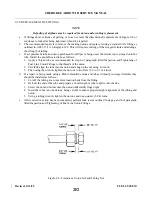
10-11. INSTALLATION OF ENGINE DRIVEN VACUUM PUMP.
CAUTION
Never install a pump that has been dropped or damaged.
Revised: 2/13/89
2F10
CHEROKEE ARROW III SERVICE MANUAL
INSTRUMENTS
Summary of Contents for ARROW III
Page 4: ...THIS PAGE INTENTIONALLY LEFT BLANK 1A4...
Page 12: ...THIS PAGE INTENTIONALLY LEFT BLANK 1A12...
Page 94: ...Figure 4 2 Wing Installation Revised 2 13 89 1D22 CHEROKEE ARROW III SERVICE MANUAL STRUCTURES...
Page 171: ...lH3 INTENTIONALLY LEFT BLANK...
Page 172: ...lH4 INTENTIONALLY LEFT BLANK...
Page 286: ...THIS PAGE INTENTIONALLY LEFT BLANK Revised 2 13 89 2A8...
Page 528: ...INTENTIONALLY LEFT BLANK 2K10 THRU 2L24 2K10...

