3. Secure all excess lead wire.
4. Now remove the top engine cowling.
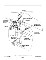
5. Mount auxiliary vacuum pump/motor assembly with band clamps. Do not tighten the clamps at
this time because adjustments may be necessary.
6. Attach and secure electrical leads to terminals on pump/motor assembly.
7. Measure hoses to obtain proper length. Allow some slack, then cut as necessary.
8. Remove all caps and plugs then attach and secure hoses to ports on pump/motor assembly.
9. Position pump/motor assembly per Figure 10-3 instructions.
10. Tighten clamps and install engine top cowling.
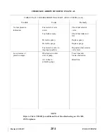
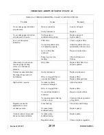
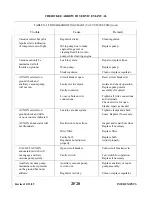
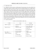
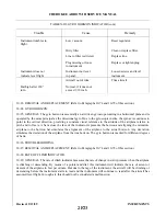
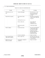
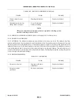
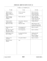
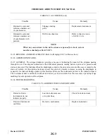
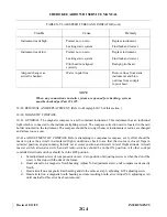
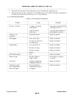
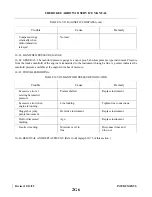
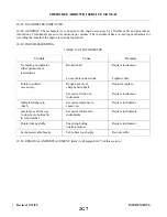
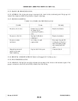
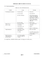
10-13. VACUUM REGULATOR VALVE. (Refer to Table X-I for Troubleshooting Instructions.) One vacuum
regulator valve is incorporated in the system to control vacuum pressure to the gyro instruments. The regulator
valve is located under the instrument panel. Access to the valve for maintenance and adjustment is gained from
below the instrument panel.
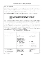
10-14. ADJUSTMENT OF VACUUM REGULATOR VALVE.
WARNING
Do not attempt adjustment of this valve with engine in operation. This
procedure may be done with the engine running provided a qualified pilot
or maintenance person is at the controls, but is considered dangerous and
not recommended by Piper.
CAUTION
Before any adjustments are made to the vacuum regulator, verify that the
system filters and lines are clean.
a.
Bend locking tabs up (if applicable) then loosen locking nut or remove protective cap from valve per
type installed.
b. Start the engine and allow for engine warm-up at a medium rpm setting.
c.
With the engine running at medium rpm, the suction gauge should indicate 5.0 ± 0.2 inches of
m e r c u r y. If the indication is not within this range, shut down the engine and adjust regulator
(clockwise to increase pressure or counterclockwise to decrease pressure).
d. Again, start the engine and repeat this procedure until an indication of 5.0 ± 0.2 inches of mercury is
obtained at a medium power setting.
NOTE
If airplane is not equipped with a suction gauge, connect a temporary gauge
of known accuracy by removing the plug from back of the artificial horizon
and attaching it there.
e.
After satisfied that pressure is adjusted correctly to 5.0 ± 0.2 inches of mercury, remove gauge and
install plug; replace protective cap and tighten locknut per type valve installed.
10-15. REMOVAL AND REPLACEMENT OF REGULATOR VALVE.
a.
Disconnect the three lines and remove mounting nut. Remove valve from airplane.
b. Install regulator in reverse order of removal.
c.
Verify that complete vacuum system is operational.
Revised: 2/13/89
2F18
CHEROKEE ARROW III SERVICE MANUAL
INSTRUMENTS
Summary of Contents for ARROW III
Page 4: ...THIS PAGE INTENTIONALLY LEFT BLANK 1A4...
Page 12: ...THIS PAGE INTENTIONALLY LEFT BLANK 1A12...
Page 94: ...Figure 4 2 Wing Installation Revised 2 13 89 1D22 CHEROKEE ARROW III SERVICE MANUAL STRUCTURES...
Page 171: ...lH3 INTENTIONALLY LEFT BLANK...
Page 172: ...lH4 INTENTIONALLY LEFT BLANK...
Page 286: ...THIS PAGE INTENTIONALLY LEFT BLANK Revised 2 13 89 2A8...
Page 528: ...INTENTIONALLY LEFT BLANK 2K10 THRU 2L24 2K10...

