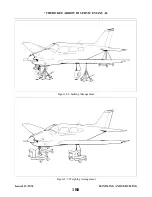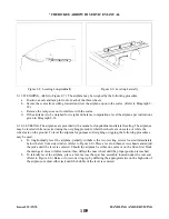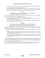
2-39. INFLATING OLEO STRUTS. After making certain that an oleo strut has sufficient fluid, attach a strut
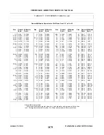
pump to the air valve and inflate the oleo strut. The strut should be inflated until the correct inches piston is
exposed with normal static load (empty weight of the airplane plus full fuel and oil) on the gears (Refer to
Paragraph 2-37.) Rock the airplane several times to ascertain that the gear settles back to the correct strut
position. (If a strut pump is not available, the airplane may be raised and line pressure from a high pressure air
system used. Lower the airplane and while rocking it, let air from the valve to bring the strut down to the
proper extension. (Before capping the valve, check for valve core leakage.)
2-40. BRAKE SYSTEM.
2-41. SERVICING BRAKE SYSTEM. The brake system incorporates a hydraulic fluid reservoir through
which the brake system is periodically serviced. Fluid is drawn from the reservoir by the brake cylinders to
maintain the volume of fluid required for maximum braking efficiency. Spongy brake pedal action is often an
indication that the brake fluid reservoir is running low on fluid. Instructions for filling the reservoir a given in
Paragraph 2-42. When found necessary to accomplish repairs to any of the brake system components, or to
bleed the system, these instructions may be found in Section VII.
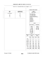
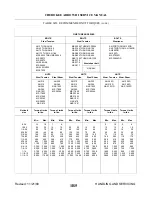
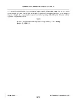
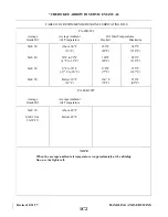
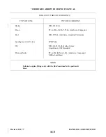
2-42. FILLING BRAKE CYLINDER RESERVOIR. The brake cylinder reservoir should be filled to the level
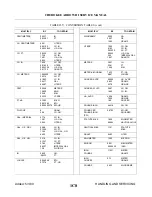
marked on reservoir, with the fluid specified in Table II-I. The reservoir, located on the left side of the firewall
in the engine compartment, should be checked at every 50-hour inspection and replenish
n e c e s s a r y. No adjustment of the brakes is necessary, though they should be checked periodically per
instructions given in Section VII.
2-43. DRAINING BRAKE SYSTEM. To drain the brake system, connect a hose to the bleeder fitting on the
bottom of the cylinder and place the other end of the line in a suitable container. Open the bleeder and slowly
pump the hand brake lever and the desired brake pedal until fluid ceases to flow. To clean the brake system,
flush with denatured alcohol.
2-44. TIRES.
2-45. SERVICING TIRES. The tires should be maintained at the pressure specified in Table II-I. When
checking tire pressure, examine the tires for wear, cuts, bruises and slippage on the wheel. The tire, tube and
wheel should be properly balanced when installed with the index mark on the tire aligned with the index mark
on the tube.
2-46. POWER PLANT.
2-47. SERVICING POWER PLANT. Regularly check the engine compartment for oil and fuel leaks, chaffing
of lines, loose wires and tightness of all parts. For cleaning of the engine compartment, refer to Paragraph 2-
23. Maintenance instructions for the power plant may be found in Section VIII or VIIIA of this manual and in
the appropriate manufacturers manuals.
Issued: 12/15/76
1B18
*CHEROKEE ARROW III SERVICE MANUAL
HANDLING AND SERVICING
Summary of Contents for ARROW III
Page 4: ...THIS PAGE INTENTIONALLY LEFT BLANK 1A4...
Page 12: ...THIS PAGE INTENTIONALLY LEFT BLANK 1A12...
Page 94: ...Figure 4 2 Wing Installation Revised 2 13 89 1D22 CHEROKEE ARROW III SERVICE MANUAL STRUCTURES...
Page 171: ...lH3 INTENTIONALLY LEFT BLANK...
Page 172: ...lH4 INTENTIONALLY LEFT BLANK...
Page 286: ...THIS PAGE INTENTIONALLY LEFT BLANK Revised 2 13 89 2A8...
Page 528: ...INTENTIONALLY LEFT BLANK 2K10 THRU 2L24 2K10...

