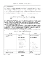
10-20. DIRECTION GYRO.
10-21. GENERAL. The directional gyro is a flight instrument incorporating an air driven gyro stabilized in the
vertical plane. The gyro is rotated at high speed by lowering the pressure in the air tight case and
simultaneously allowing atmospheric air pressure to enter the instrument against the gyro buckets. Due to
gyroscopic inertia, the spin axis continues to point in the same direction even though the aircraft yaws to the
right or left. This relative motion between the gyro and the instrument case is shown on the instrument dial
which is similar to a compass card. The dial, when set to agree with the airplane magnetic compass provides a
positive indication free from swing and turning error. However, the directional gyro has no sense of direction
and must be set to the magnetic compass, since the magnetic compass is subject to errors due to magnetic
fields, electric instruments, etc., the directional gyro is only accurate for the heading it has been set for. If the
gyro is set on 270°, for instance, and the aircraft is turned to some other heading, there can be a large error
between the gyro and the magnetic compass due to the error in compass compensation, the will appear as gyro
precession. The gyro should only be checked on the heading on which it was first set, also due to internal
friction, spin axis error, air turbulence and airflow, the gyro should be set at least every 15 minutes for accurate
operation, whether it has drifted or not.
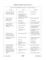
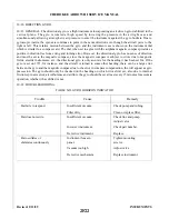
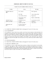
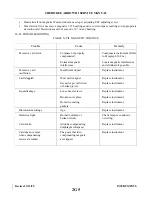
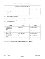
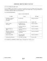
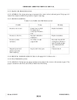
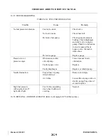
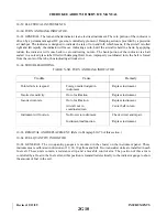
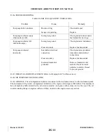
10-22. TROUBLESHOOTING.
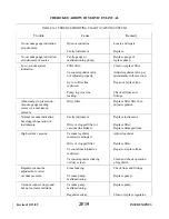
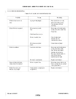
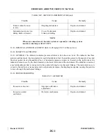
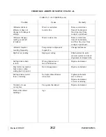
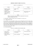
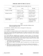
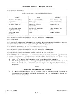
TABLE X-II. GYRO HORIZON INDICATOR
Trouble
Cause
Remedy
Bar fails to respond.
Insufficient vacuum.
Check pump and tubing.
Filter dirty.
Clean or replace filter.
Bar does not settle.
Insufficient vacuum.
Check line and pump.
Adjust valve.
Incorrect instrument.
Check part number.
Defective instrument.
Replace.
Bar oscillates or
Instrument loose in
Tighten mounting
shimmies continuously.
panel.
screws.
Vacuum too high.
Adjust valve.
Defective mechanism.
Replace instrument.
Revised: 2/13/89
2F22
CHEROKEE ARROW III SERVICE MANUAL
INSTRUMENTS
Summary of Contents for ARROW III
Page 4: ...THIS PAGE INTENTIONALLY LEFT BLANK 1A4...
Page 12: ...THIS PAGE INTENTIONALLY LEFT BLANK 1A12...
Page 94: ...Figure 4 2 Wing Installation Revised 2 13 89 1D22 CHEROKEE ARROW III SERVICE MANUAL STRUCTURES...
Page 171: ...lH3 INTENTIONALLY LEFT BLANK...
Page 172: ...lH4 INTENTIONALLY LEFT BLANK...
Page 286: ...THIS PAGE INTENTIONALLY LEFT BLANK Revised 2 13 89 2A8...
Page 528: ...INTENTIONALLY LEFT BLANK 2K10 THRU 2L24 2K10...

