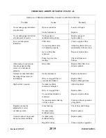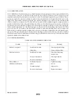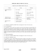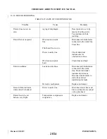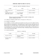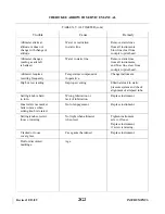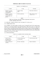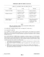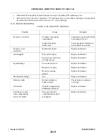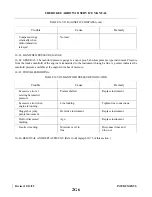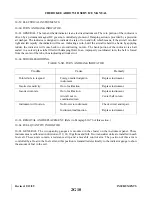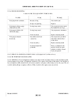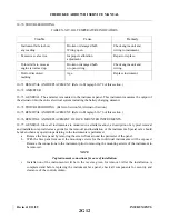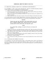
TABLE X-VI. AIRSPEED TUBES AND INDICATOR (cont)
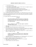
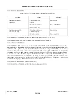
Trouble
Cause
Remedy
Instrument reads high.
Pointer not on zero.
Replace instrument.
Leaking static system.
Find leak and correct.
Instrument reads low.
Pointer not on zero.
Replace instrument.
Leaking static system.
Find leak and correct.
Pitot head not aligned
Realign pitot head.
correctly.
Airspeed changes as
Water in pitot line.
Remove lines from static
aircraft is banked.
instruments and blow
out lines from cockpit
to pitot head.
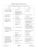
NOTE
When any connections in static system are opened for checking, system
must be checked per Part 23.1325.
10-39. REMOVAL AND REPLACEMENT. (Refer to Paragraph 10-76 of this section.)
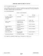
10-40. MAGNETIC COMPASS.
10-41. GENERAL. The magnetic compass is a self-contained instrument. This instrument has an individual
light which is connected to the instrument lighting circuit. The compass correction card is located in the card
holder mounted on the instrument. The compass should be swung whenever instruments or radios are changed
and at least once a year.
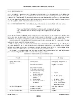
10-41a. ADJUSTMENT OF COMPASS. Before attempting to compensate compass, every effort should be
made to place the aircraft in simulated flight conditions; check to see that the doors are closed, flaps in
retracted position, engine running, throttle set at cruise position and aircraft in level flight attitude. Aircraft
master switch, alternator switch and all radio switches should be in the ON position. All other cockpit
controlled electrical switches should be in the OFF position.
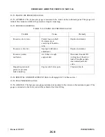
a.
Set adjustment screws of compensator on zero. Zero position of adjusting screws is when the dot of the
screw is lined up with the dot of the frame.
b. Head aircraft on a magnetic North heading. Adjust N-S adjustment screw until compass reads exactly
North.
c.
Head aircraft on a magnetic East heading and do the same as step b, adjusting E-W adjusting screw.
d. Head aircraft on a magnetic South heading and note resulting South error. Adjust N-S adjusting screw
until one-half of this error has been removed.
Revised: 2/13/89
2G4
CHEROKEE ARROW III SERVICE MANUAL
INSTRUMENTS
Summary of Contents for ARROW III
Page 4: ...THIS PAGE INTENTIONALLY LEFT BLANK 1A4...
Page 12: ...THIS PAGE INTENTIONALLY LEFT BLANK 1A12...
Page 94: ...Figure 4 2 Wing Installation Revised 2 13 89 1D22 CHEROKEE ARROW III SERVICE MANUAL STRUCTURES...
Page 171: ...lH3 INTENTIONALLY LEFT BLANK...
Page 172: ...lH4 INTENTIONALLY LEFT BLANK...
Page 286: ...THIS PAGE INTENTIONALLY LEFT BLANK Revised 2 13 89 2A8...
Page 528: ...INTENTIONALLY LEFT BLANK 2K10 THRU 2L24 2K10...

