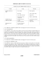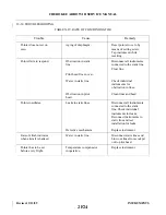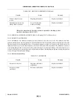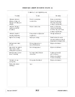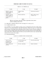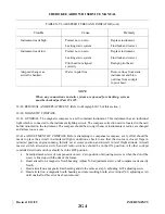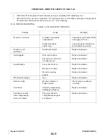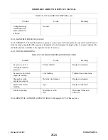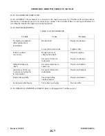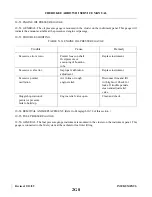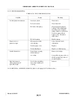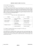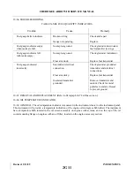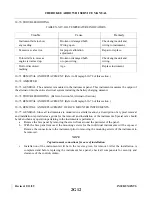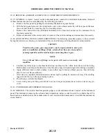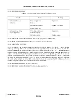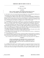
10-78. REMOVAL AND REPLACEMENT OF CLUSTER MOUNTED INSTRUMENTS.
10-79. GENERAL. A cluster, located on the instrument panel, contains five individual instruments. Removal
of these instruments can be accomplished by the following procedure:
a.
Remove the face panel by pulling from retaining channels at top and bottom.
b. With the face panel removed, the clear plastic cover on the cluster assembly will be exposed. Remove
the cover and cluster by removing the two mounting screws.
c.
Remove the connection to the individual instrument to be removed and remove the instrument from
the cluster assembly.
d. Replace instrument in the reverse order of removal. Check all mountings and connections for security.
10-80. GYRO FITTING INSTALLATION PROCEDURE. The following procedure applies to those aircraft
having the Edo-Aire air driven gyro installation. The use of teflon tape on fitting threads is recommended.
CAUTION
Permit no oil, grease, pipe compound or any foreign material to enter ports
prior to installation of fittings. Make certain all air lines are clean and free
of foreign particles and/or residue before connecting lines to gyro.
NOTE
Use of thread lube on fittings or in ports will create a warranty void
condition.
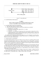
a.
Carefully lay teflon tape on the threads allowing one thread to be visible from the end of the fitting.
Hold in place and wrap in the direction of the threads so tape will remain tight when fitting is installed.
b. Apply sufficient tension while winding to assure that tape forms into thread grooves. One full wrap
plus 1/2 inch overlap is sufficient.
c.
After wrap is completed, maintain tension and tear tape by pulling in direction of wrap. The resulting
ragged end is the key to the tape staying in place.
d. Press the tape well into the threads.
e.
Screw fitting into port being careful not to exceed torque requirements as noted on decal on gyro
cover.
10-81. CYLINDER HEAD TEMPERATURE GAUGE.
10-82. GENERAL. The cylinder head temperature gauge is in the instrument cluster, located on the instrument
panel. This instrument measures the cylinder head temperature using a sender located in a cylinder head. The
head location is determined by the manufacturer. It is an electrical instrument and is wired thru the instruments
circuit breaker.
Revised: 2/13/89
2G13
CHEROKEE ARROW III SERVICE MANUAL
INSTRUMENTS
Summary of Contents for ARROW III
Page 4: ...THIS PAGE INTENTIONALLY LEFT BLANK 1A4...
Page 12: ...THIS PAGE INTENTIONALLY LEFT BLANK 1A12...
Page 94: ...Figure 4 2 Wing Installation Revised 2 13 89 1D22 CHEROKEE ARROW III SERVICE MANUAL STRUCTURES...
Page 171: ...lH3 INTENTIONALLY LEFT BLANK...
Page 172: ...lH4 INTENTIONALLY LEFT BLANK...
Page 286: ...THIS PAGE INTENTIONALLY LEFT BLANK Revised 2 13 89 2A8...
Page 528: ...INTENTIONALLY LEFT BLANK 2K10 THRU 2L24 2K10...

