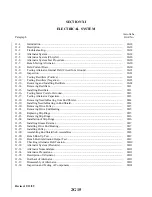
SECTION XI
ELECTRICAL SYSTEM
WARNING
When servicing or inspecting vendor equipment installed in Piper aircraft, it
is the user’s responsibility to refer to the applicable vendor publication.
11-1. Introduction. This section contains instructions and schematics for correcting difficulties which may arise
in the operation of the electrical system in PA-28R-201 and PA-28R-201T airplanes.
The instructions are organized so the mechanic can refer to: Description and Principles of Operation for a
basic understanding of the various electrical system; Troubleshooting for a methodical approach in locating the
d i fficulty; Corrective Maintenance of removal, repair and installation of components; and adjustments and
tests for operation of the repaired system. Schematics for the individual systems are located at the end of this
section. For information concerning electronic equipment, refer to Section XII, Electronics.
11-2. DESCRIPTION. Electrical power is supplied by a 14 volt, direct current, negative ground electrical
system. A 12 volt battery is incorporated into the system to furnish power for starting and as a reserve power
source in case of alternator failure. Access to the battery is through the aft side of the baggage compartment.
The electrical generating system consists of an engine driven 60 amp alternator for the PA-28R-201 or a 65
amp alternator for the PA-28R-201T. A solid state voltage regulator maintains the system bus voltage at 14
volts. Also incorporated is an overvoltage relay, which prevents damage to electrical and avionics equipment
in case of a regulator malfunction. The loads from the electrical bus systems are protected by manual reset type
circuit breakers mounted on the lower right hand side of the instrument panel.
The master switch must be ON before any electrical equipment will operate. The master switch controls
the battery relay and field circuit. This switch is a double pole single throw type.
The lighting system for night time operation is optional equipment and consists of a landing light,
anticollision lights and navigation lights.
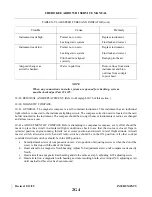
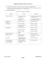
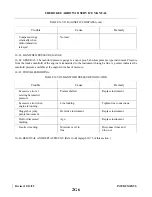
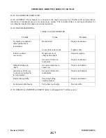
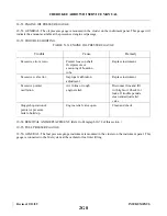
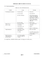
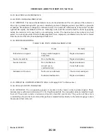
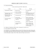
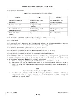
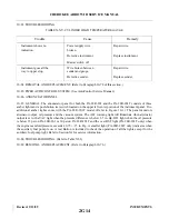
11-3. TROUBLESHOOTING. Troubles peculiar to the electrical system are listed in Table XI-V at the back of
this section along with their probable causes and suggested remedies. The wiring diagrams included at the end
of this section will give physical breakdown of the different electrical circuits used in these airplanes.
After the trouble has been corrected, check the entire system for security and operation of its components.
WARNING
All checks and adjustments of the alternator and/or its components should
be made with the engine stopped. Therefore, to complete some checks or
adjustments, it will be necessary to remove these units from the airplane and
place on a test stand.
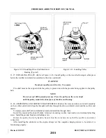
11-4. ALT E R N ATOR SYSTEM. The PA-28R-201 alternator is located on the front lower right side of the
engine and utilizes a belt drive from the engine crankshaft. The PA-28R-201T alternator is mounted on the
accessory case at the rear of the engine. Many advantages, both in operation and maintenance, are derived
from this system. The main advantage is that full electrical power output is available regardless of engine rpm.
Revised: 2/13/89
2G18
CHEROKEE ARROW III SERVICE MANUAL
ELECTRICAL SYSTEM
Summary of Contents for ARROW III
Page 4: ...THIS PAGE INTENTIONALLY LEFT BLANK 1A4...
Page 12: ...THIS PAGE INTENTIONALLY LEFT BLANK 1A12...
Page 94: ...Figure 4 2 Wing Installation Revised 2 13 89 1D22 CHEROKEE ARROW III SERVICE MANUAL STRUCTURES...
Page 171: ...lH3 INTENTIONALLY LEFT BLANK...
Page 172: ...lH4 INTENTIONALLY LEFT BLANK...
Page 286: ...THIS PAGE INTENTIONALLY LEFT BLANK Revised 2 13 89 2A8...
Page 528: ...INTENTIONALLY LEFT BLANK 2K10 THRU 2L24 2K10...

