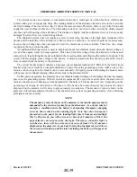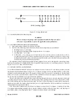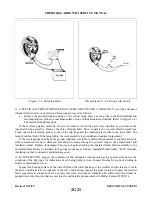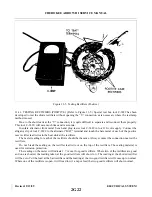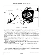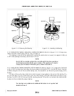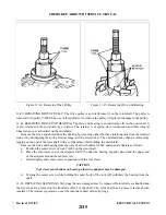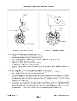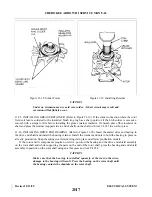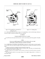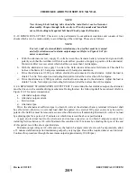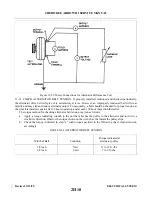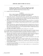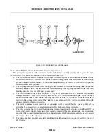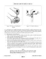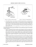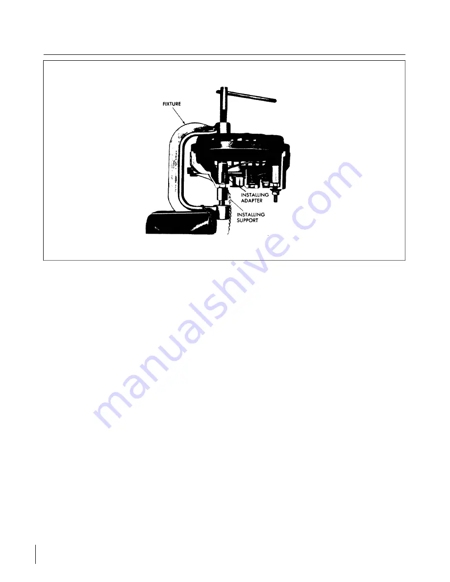
Figure 11-9. Installing Rectifiers
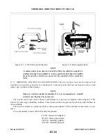
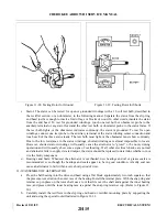
11-14. REMOVING RECTIFIERS. After cutting the lead from the malfunctioning rectifier, position the
fixture with the rectifier to be removed over the fixture anvil.
Position the removing adapter SP-3821 around the rectifier. Rotate the threaded screw clockwise. As the
screw approaches the removing adapter, guide its shank into the hole in the end of the screw.
Just before the downward motion of the screw bottoms, recheck the adapter to be sure it is in the proper
position. Then continue to rotate the screw until the rectifier is free of the end shield or heat sink.
Reverse the screw by rotating it counterclockwise. Remove adapter and old rectifier.
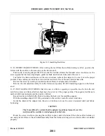
Remove the end shield assembly from the fixture and position SP-3820 installing support on the fixture
anvil.
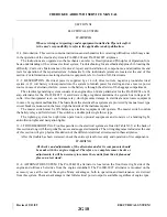
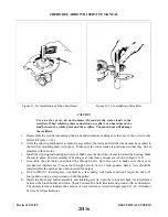
11-15. INSTALLING RECTIFIERS. Start the new rectifier as squarely as possible into the hole the old
rectifier was removed from after first checking to be sure it is of the proper polarity. The negative rectifiers are
marked with black numerals and the positive with red.
Reposition the end shield in the fixture, locating the hole over the installing support.
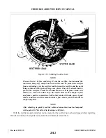
With the installing adapter SP-3818 positioned on the rectifier, rotate the screw clockwise.
Guide the shank of the adapter into the screw. Continue to move the screw downward until just before
bottoming.
CAUTION
Check carefully to be certain that the adapter is positioned properly over the
rectifier and the rectifier is started squarely in the hole.
Rotate the screw clockwise pressing the rectifier in place until it bottoms. When the rectifier bottoms, it
can easily be felt. Remove the end shield assembly from the fixture and inspect to see that rectifier is installed
properly.
Revised: 2/13/89
2H1
CHEROKEE ARROW III SERVICE MANUAL
ELECTRICAL SYSTEM
Summary of Contents for ARROW III
Page 4: ...THIS PAGE INTENTIONALLY LEFT BLANK 1A4...
Page 12: ...THIS PAGE INTENTIONALLY LEFT BLANK 1A12...
Page 94: ...Figure 4 2 Wing Installation Revised 2 13 89 1D22 CHEROKEE ARROW III SERVICE MANUAL STRUCTURES...
Page 171: ...lH3 INTENTIONALLY LEFT BLANK...
Page 172: ...lH4 INTENTIONALLY LEFT BLANK...
Page 286: ...THIS PAGE INTENTIONALLY LEFT BLANK Revised 2 13 89 2A8...
Page 528: ...INTENTIONALLY LEFT BLANK 2K10 THRU 2L24 2K10...

