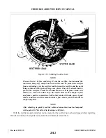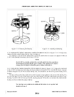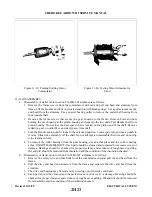
NOTE
New through bolt locking tabs should be installed at each alternator
disassembly. Torque through bolts evenly to 25 inch pounds and bend both
ears of the locking tabs against bolt head. Check proper belt tension.
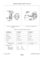
11-29. BENCH RUN-UP TEST. This test it to be performed at room ambient conditions and consists of four
checks which are to be made quickly to avoid heating of the windings. These are as follows:
NOTE
For test c and d, external field excitation may be used but must be removed
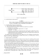
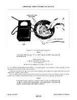
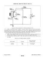
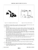
and self excitation used to obtain output amperes. (Refer to Figure 11-22 for
meter connections.)
a.
With the alternator at rest, supply 15-volts between the alternator battery terminal and ground with
polarity such that the rectifiers will block current flow (positive of supply to positive of the alternator).
Monitor rectifier reverse current which shall be not more than 1 milliampere.
b. With the alternator at rest, apply 15-volts to the field circuit and monitor field current. This shall be
between the limits of 3.3-amperes minimum and 3.6-amperes maximum.
c.
Drive the alternator at 1500 rpm with an electrical load connected to the alternator. Adjust the load to
obtain 15-volts. Net output (not including field current) shall be not less than 26.5-amperes.
d. Drive the alternator at 2500 rpm with an electrical load connected to the alternator. Adjust the load to
obtain 15-volts. Net output (not including field current) shall be not less than 49.0-amperes.
11-30. BENCH HOT STABILIZATION OUTPUT TEST. To determine the hot stabilized output, the alternator
must be driven with a suitable driving mechanism. During this test, the following shall be monitored: (Refer to
Figure 11-22 for meter connections.)
a.
Alternator output voltage.
b. Alternator output current.
c.
Field current.
d. Alternator rpm.
Drive the alternator at sufficient rpm to obtain 14-volts at the alternator battery terminal. Alternator shall
be self excited, otherwise no external load shall be applied. An external DC power source may be used to
polarize the field but must be removed as soon as the alternator is self sustaining. Maintain 14-volts at no load
by adjusting rpm for a period of 15 minutes, at which time record the above specified data.
Apply an electrical load to the alternator and increase speed so as to obtain 5-amperes output (not
including field excitation) at 14-volts. Maintain this condition for 15 minutes by adjusting the rpm. At the end
of this period, record the above specified data.
Maintain output voltage at 14-volts and vary the load in 5-ampere intervals. At each 5-amp intervals, allow
a 15 minute stabilization period maintaining output by varying rpm. Record the required data at each interval.
Continue this procedure through the maximum output (approximately 10,000 rpm).
Revised: 2/13/89
2H9
CHEROKEE ARROW III SERVICE MANUAL
ELECTRICAL SYSTEM
Summary of Contents for ARROW III
Page 4: ...THIS PAGE INTENTIONALLY LEFT BLANK 1A4...
Page 12: ...THIS PAGE INTENTIONALLY LEFT BLANK 1A12...
Page 94: ...Figure 4 2 Wing Installation Revised 2 13 89 1D22 CHEROKEE ARROW III SERVICE MANUAL STRUCTURES...
Page 171: ...lH3 INTENTIONALLY LEFT BLANK...
Page 172: ...lH4 INTENTIONALLY LEFT BLANK...
Page 286: ...THIS PAGE INTENTIONALLY LEFT BLANK Revised 2 13 89 2A8...
Page 528: ...INTENTIONALLY LEFT BLANK 2K10 THRU 2L24 2K10...

