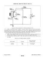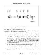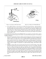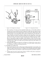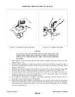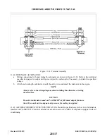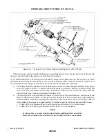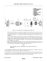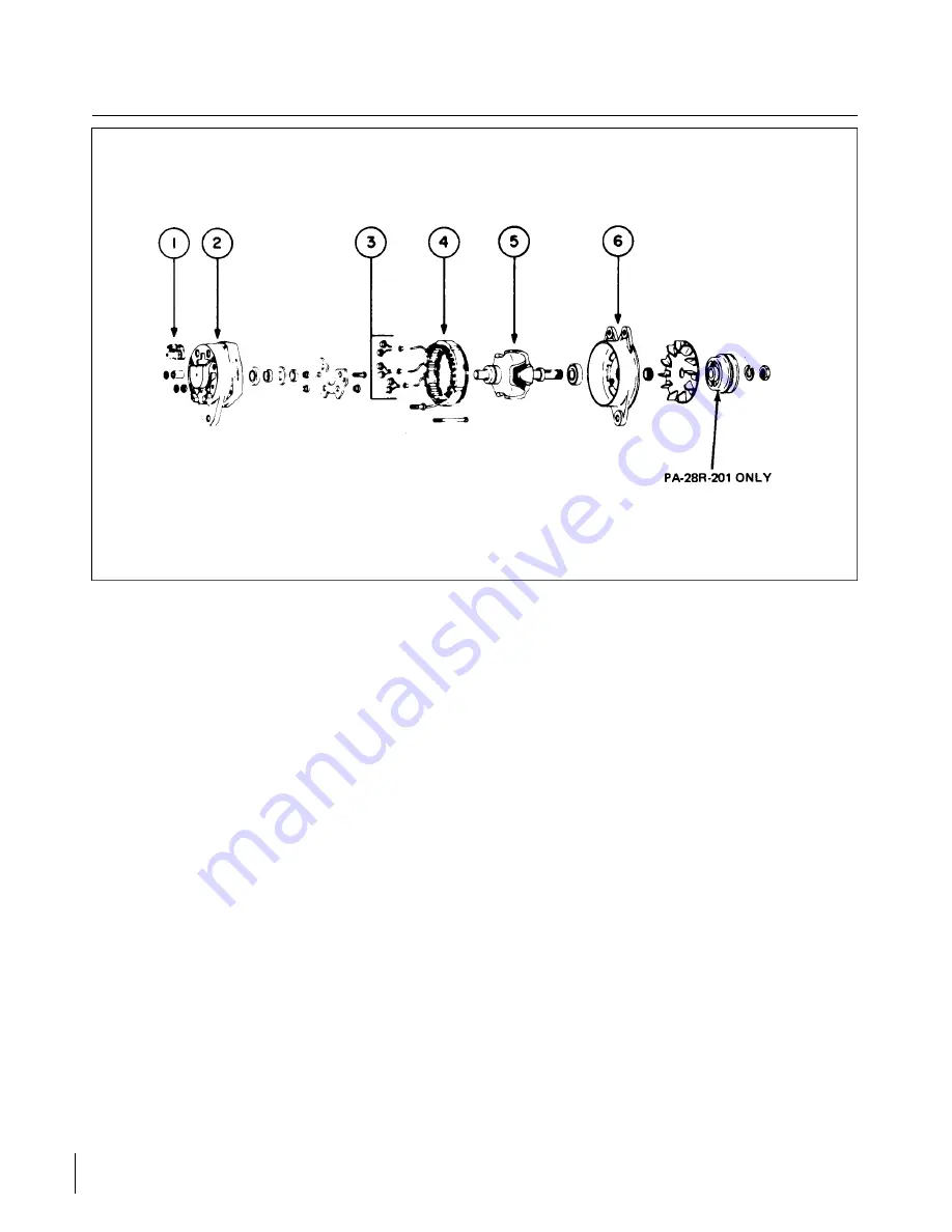
Figure 11-23. Exploded View of Alternator.
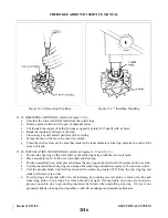
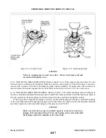
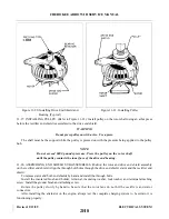
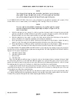
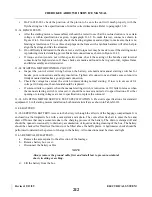
11-35. DESCRIPTION OF ALTERNATOR. (Refer to Figure 11-23.)
the rectifiers (3), the stator (4), the rotor (5) and the drive end head (6).
a.
The brush holder assembly contains two brushes, two brush springs, a brush holder and insulator. One
brush is connected to a terminal stud and is insulated from ground. The other brush is connected to
ground through the brush holder. The brush and holder assembly can easily be removed for inspection
or brush replacement purposes.
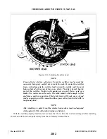
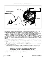
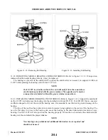
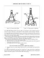
b. The slip ring end head provides the mounting for the rectifiers and rectifier mounting plate, output and
auxiliary terminal studs, and the brush and holder assembly. The slip ring end head contains a roller
bearing and outer race assembly and a grease seal.
c.
The rectifiers used in these units are rated at 150 peak inverse voltage (P.I.V.) minimum for transient
voltage protection. Three positive rectifiers are mounted in the rectifier mounting plate while the three
negative rectifiers are mounted in the slip ring end head. Each pair of rectifiers is connected to a stator
lead with high temperature solder. The stator leads are anchored to the rectifier mounting plate with
epoxy cement for vibration protection.
d. The stator contains a special lead which is connected to the center of the three phase windings. The
stator has been treated with a special epoxy varnish for high temperature resistance.
e.
The rotor contains the slip ring end bearing inner race and spacer on the slip ring end of the shaft. The
rotor winding and winding leads have been specially treated with a high temperature epoxy cement to
provide vibration and temperature resistance characteristics. High temperature solder is used to secure
the winding leads to the slip rings.
f.
The drive end head supports a sealed, prelubricated ball bearing in which the drive end of the rotor
shaft rotates.
Revised: 2/13/89
2H12
CHEROKEE ARROW III SERVICE MANUAL
ELECTRICAL SYSTEM
Summary of Contents for ARROW III
Page 4: ...THIS PAGE INTENTIONALLY LEFT BLANK 1A4...
Page 12: ...THIS PAGE INTENTIONALLY LEFT BLANK 1A12...
Page 94: ...Figure 4 2 Wing Installation Revised 2 13 89 1D22 CHEROKEE ARROW III SERVICE MANUAL STRUCTURES...
Page 171: ...lH3 INTENTIONALLY LEFT BLANK...
Page 172: ...lH4 INTENTIONALLY LEFT BLANK...
Page 286: ...THIS PAGE INTENTIONALLY LEFT BLANK Revised 2 13 89 2A8...
Page 528: ...INTENTIONALLY LEFT BLANK 2K10 THRU 2L24 2K10...

