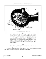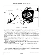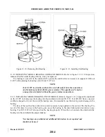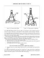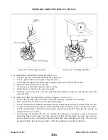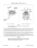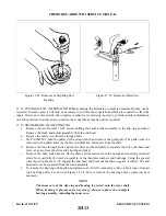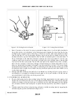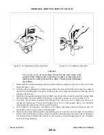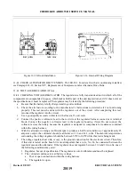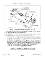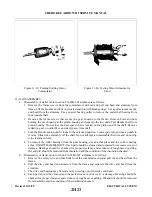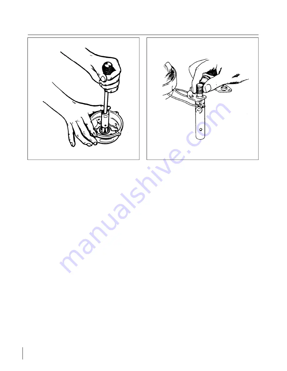
Figure 11-24. Removal of Slip Ring End
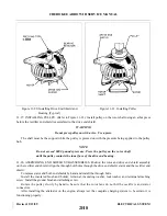
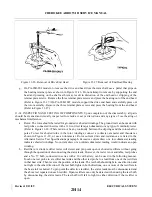
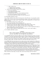
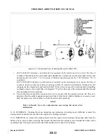
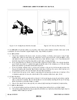
Figure 11-25. Removal of Rectifier
Bearing
11-36. OVERHAUL OF ALT E R N ATOR. When repairing the alternator, complete disassembly may not be
required. In some cases, it will only be necessary to perform those operations which are required to effect the
repair. However, in this section, the complete overhaul is covered step-by-step to provide detailed information
on each operation. In actual service practice, these operations may be used as required.
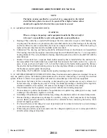
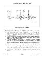
11-37. DISASSEMBLY OF ALTERNATOR.
a.
Remove the two Number 10-24 screws holding the brush holder assembly in the slip ring end head.
Remove the brush and holder assembly from the end head.
b. Remove the safety wire from the through bolts.
c.
On PA-28R-201, hold the pulley with a strap wrench and remove the pulley nut. The pulley must be
removed with a puller. Remove the fan, woodruff key and spacer from the shaft.
d. Remove the four through bolts and tap the drive end head lightly to separate the drive end head and
rotor, as a unit, from the stator and slip ring end head.
e.
Remove the nuts, lockwashers, flat washers and insulators from the output and auxiliary terminal
studs. Note carefully the correct assembly of the insulator washers and bushings. Using the special
tools shown in Figure 11-25, support the end head and press out the three negative rectifiers. The end
head can now be separated from the stator assembly.
f.
To remove the slip ring end bearing and grease seal, it will be necessary to have a hook type or impact
type bearing puller as shown in Figure 11-24. Do not remove the bearing unless replacement is
necessary.
NOTE
The inner race of the slip ring end bearing is pressed onto the rotor shaft.
When bearing replacement is necessary, always replace the complete
bearing assembly, including the inner race.
Revised: 2/13/89
2H13
CHEROKEE ARROW III SERVICE MANUAL
ELECTRICAL SYSTEM
Summary of Contents for ARROW III
Page 4: ...THIS PAGE INTENTIONALLY LEFT BLANK 1A4...
Page 12: ...THIS PAGE INTENTIONALLY LEFT BLANK 1A12...
Page 94: ...Figure 4 2 Wing Installation Revised 2 13 89 1D22 CHEROKEE ARROW III SERVICE MANUAL STRUCTURES...
Page 171: ...lH3 INTENTIONALLY LEFT BLANK...
Page 172: ...lH4 INTENTIONALLY LEFT BLANK...
Page 286: ...THIS PAGE INTENTIONALLY LEFT BLANK Revised 2 13 89 2A8...
Page 528: ...INTENTIONALLY LEFT BLANK 2K10 THRU 2L24 2K10...

