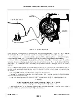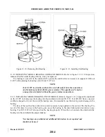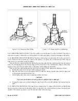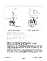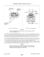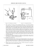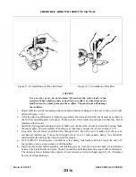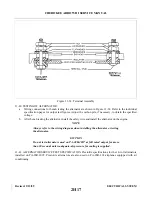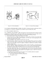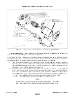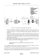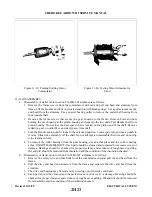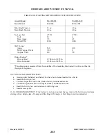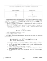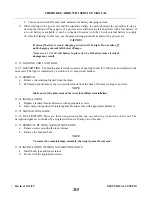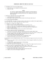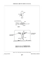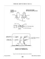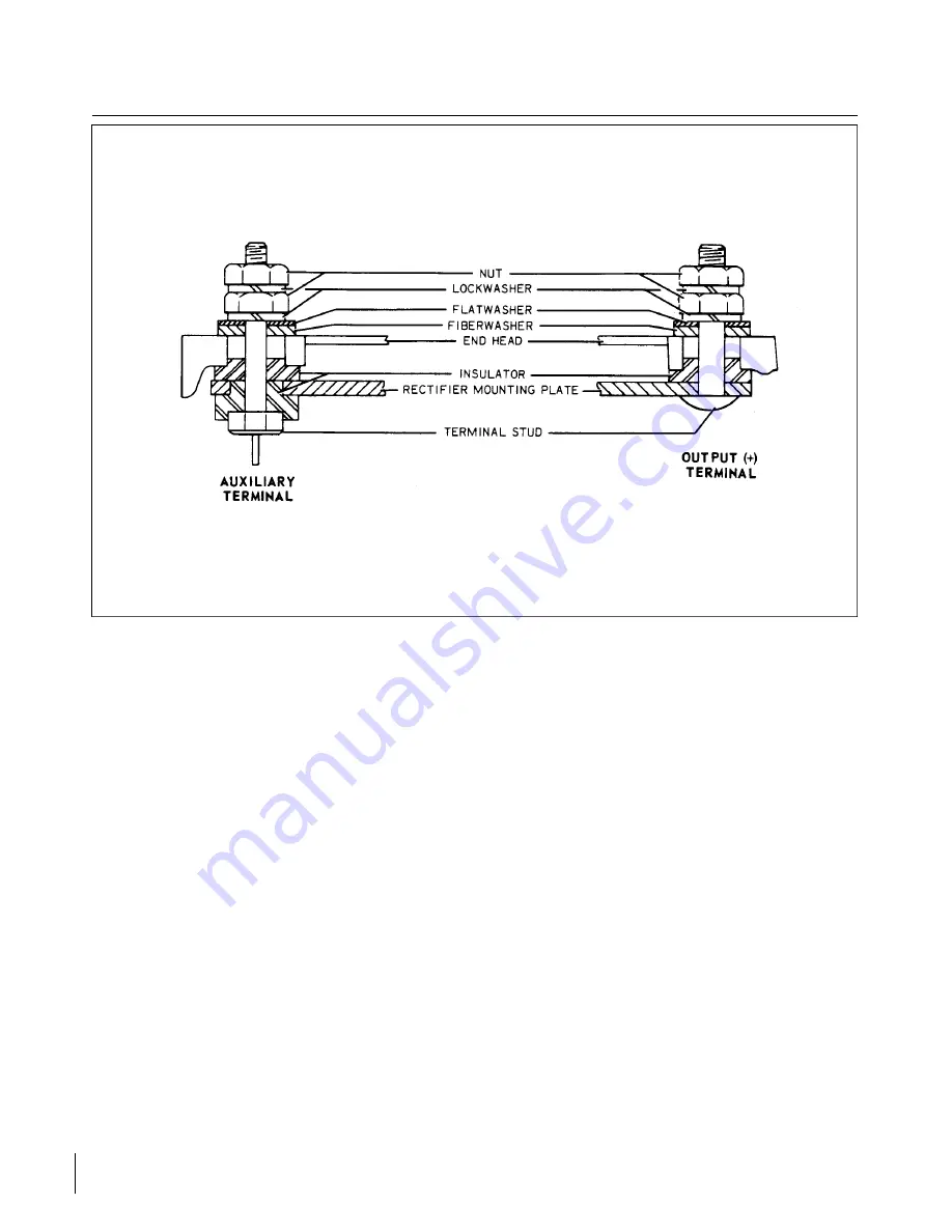
Figure 11-32. Terminal Assembly
11-40. TESTING OF ALTERNATOR.
a.
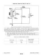
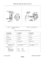
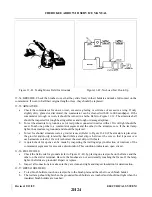
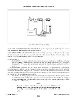
Wiring connections for bench testing the alternator are shown in Figure 11-34. Refer to the individual
specification pages for output test figures. Adjust the carbon pile, if necessary, to obtain the specified
voltage.
b. After bench testing the alternator, install the safety wire and install the alternator on the engine.
NOTE
Always refer to the wiring diagram when installing the alternator or testing
the alternator.
CAUTION
Do not test alternators used on PA-28R-201T at full rated output for more
than 30 seconds unless adequate-air pressure for cooling is supplied.
11-41. ALTERNATOR SERVICE TEST SPECIFICATION. Prestolite specifications for the 14-volt alternators
installed on PA - 2 8 R - 2 0 1 T. Prestolite alternators are also used on PA-28R-201 airplanes equipped with air
conditioning.
Revised: 2/13/89
2H17
CHEROKEE ARROW III SERVICE MANUAL
ELECTRICAL SYSTEM
Summary of Contents for ARROW III
Page 4: ...THIS PAGE INTENTIONALLY LEFT BLANK 1A4...
Page 12: ...THIS PAGE INTENTIONALLY LEFT BLANK 1A12...
Page 94: ...Figure 4 2 Wing Installation Revised 2 13 89 1D22 CHEROKEE ARROW III SERVICE MANUAL STRUCTURES...
Page 171: ...lH3 INTENTIONALLY LEFT BLANK...
Page 172: ...lH4 INTENTIONALLY LEFT BLANK...
Page 286: ...THIS PAGE INTENTIONALLY LEFT BLANK Revised 2 13 89 2A8...
Page 528: ...INTENTIONALLY LEFT BLANK 2K10 THRU 2L24 2K10...

