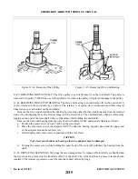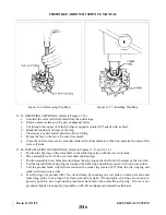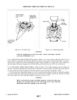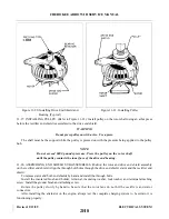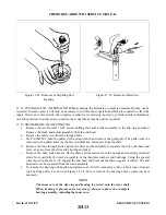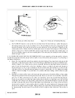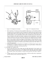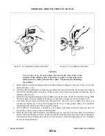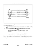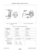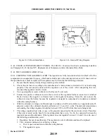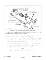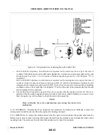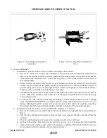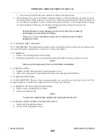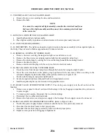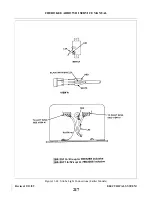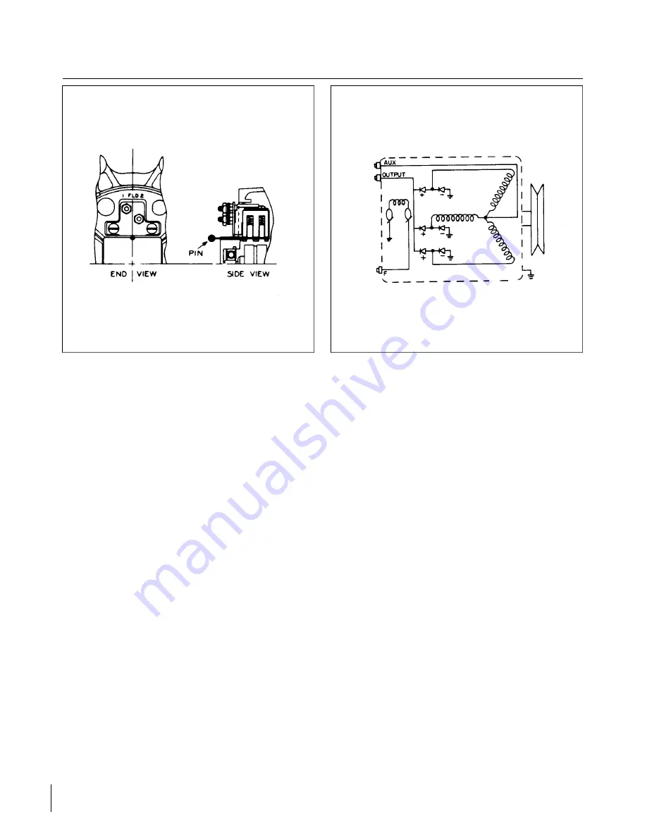
Figure 11-35. Brush Installation
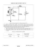
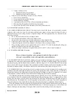
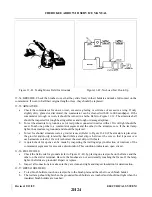
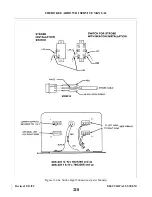
Figure 11-36. Internal Wiring Diagram
11-42. CHECK ALT E R N ATOR BELT TENSION. PA-28R-201. For aircraft with air conditioning installed,
see Paragraph 14-22, Section XIV, Replacement of Compressor and/or Alternator Drive Belts.
11-43. VOLTAGE REGULATOR. (Wico)
11-44. CHECKING VOLTAGE REGULATOR. The regulator is a fully transistorized unit in which all of the
components are encapsulated in epoxy, which makes field repair of the unit impractical, and if it does not meet
the specifications, it must be replaced. The regulator may be tested by the following procedure:
a.
Be sure that the battery is fully charged and in good condition.
b. Check the alternator according to the manufacturer’s instructions to determine if it is functioning
p r o p e r l y. This test must be done with the regulator out of the circuit. After completing this test,
reconnect the regulator into the circuit.
c.
Use a good quality accurate voltmeter with at least a 15-volt scale.
d. Connect the positive voltmeter lead to the red wire at the regulator harness connector or terminal
block. Connect the negative voltmeter lead to the regulator housing. (Note) Do not connect the
voltmeter across the battery because the regulator is designed to compensate for resistance contained
within the wiring harness.
e.
With the alternator turning at sufficient rpm to produce a half load condition, or approximately 25
amperes output, the voltmeter should read between 13.6 and 14.3-volts. The ambient temperatures
surrounding the voltage regulator should be between 50°F to 100°F while this test is being made.
f.
The voltage regulator heat sink, or case, is the ground connection for the electronic circuit. Therefore,
if this unit is tested on the bench it is most important that a wire, No. 14, be connected between the
regulator case and the alternator. If the regulator does not regulate between 13.6 and 14.4-volts, one of
the following conditions may exist:
1. Regulates, but out of specification. The regulator is out of calibration and must be replaced.
2. The voltmeter continues to read battery voltage.
a.
Poor or open connections within the wiring harness.
b. The regulator is open.
Revised: 2/13/89
2H19
CHEROKEE ARROW III SERVICE MANUAL
ELECTRICAL SYSTEM
Summary of Contents for ARROW III
Page 4: ...THIS PAGE INTENTIONALLY LEFT BLANK 1A4...
Page 12: ...THIS PAGE INTENTIONALLY LEFT BLANK 1A12...
Page 94: ...Figure 4 2 Wing Installation Revised 2 13 89 1D22 CHEROKEE ARROW III SERVICE MANUAL STRUCTURES...
Page 171: ...lH3 INTENTIONALLY LEFT BLANK...
Page 172: ...lH4 INTENTIONALLY LEFT BLANK...
Page 286: ...THIS PAGE INTENTIONALLY LEFT BLANK Revised 2 13 89 2A8...
Page 528: ...INTENTIONALLY LEFT BLANK 2K10 THRU 2L24 2K10...

