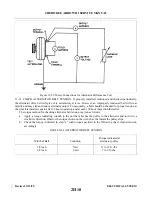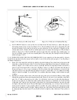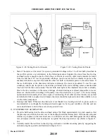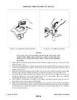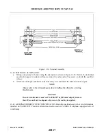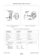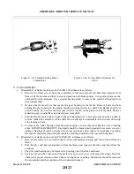
Figure 11-41. Testing Motor Field for Grounds
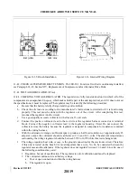
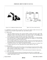
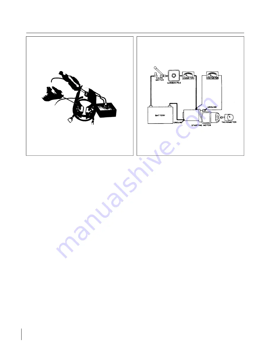
Figure 11-42. No-Load Test Hook-Up
11-54. BRUSHES. Check the brushes to see that they slide freely in their holders and make full contact on the
commutator. If worn to half their original length or less, they should be replaced.
11-55. ARMATURE.
a.
Check the commutator for uneven wear, excessive glazing or evidence of excessive arcing. If only
slightly dirty, glazed or discolored, the commutator can be cleaned with 00 to 000 sandpaper. If the
commutator is rough or worn, it should be turned in a lathe. Refer to Figure 11-39. The armature shaft
should be inspected for rough bearing surfaces and rough or damaged splines.
b. To test the armature for grounds, a set of test probes connected in series with a 110-volt light should be
used. Touch one probe to a commutator segment and the other to the armature core. If the test lamp
lights, the armature is grounded and should be replaced.
c.
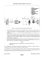
To test for shorted armature coils, a growler is used. (Refer to Figure 11-40.) The armature is placed on
the growler and slowly rotated by hand while a steel strip is held over the core so that it passes over
each armature core slot. If a coil is shorted, the steel strip will vibrate.
d. A quick check for opens can be made by inspecting the trailing edge (in direction of rotation) of the
commutator segments for excessive discoloration. This condition indicates an open circuit.
11-56. FIELD COILS.
a.
Check the field coils for grounds (refer to Figure 11-41) by placing one test probe on the frame and the
other on the starter terminal. Be sure the brushes are not accidentally touching the frame. If the lamp
lights, the fields are grounded. Repair or replace.
b. Inspect all connections to make sure they are clean and tight and inspect insulation for deterioration.
11-57. BRUSH HOLDERS.
a.
To test brush holders, touch one test probe to the brush plate and the other to each brush holder.
b. The test lamp should light when the grounded brush holders are touched and should not light when the
insulated brush holders are touched.
Revised: 2/13/89
2H24
CHEROKEE ARROW III SERVICE MANUAL
ELECTRICAL SYSTEM
Summary of Contents for ARROW III
Page 4: ...THIS PAGE INTENTIONALLY LEFT BLANK 1A4...
Page 12: ...THIS PAGE INTENTIONALLY LEFT BLANK 1A12...
Page 94: ...Figure 4 2 Wing Installation Revised 2 13 89 1D22 CHEROKEE ARROW III SERVICE MANUAL STRUCTURES...
Page 171: ...lH3 INTENTIONALLY LEFT BLANK...
Page 172: ...lH4 INTENTIONALLY LEFT BLANK...
Page 286: ...THIS PAGE INTENTIONALLY LEFT BLANK Revised 2 13 89 2A8...
Page 528: ...INTENTIONALLY LEFT BLANK 2K10 THRU 2L24 2K10...

