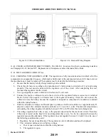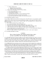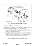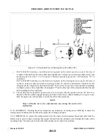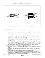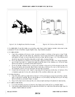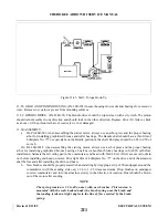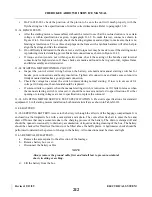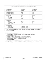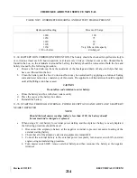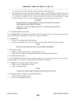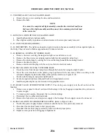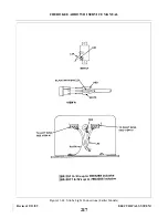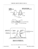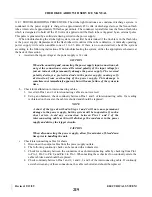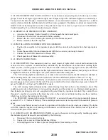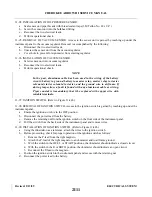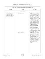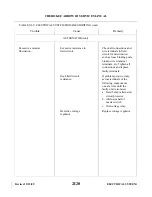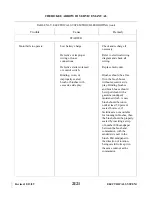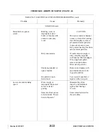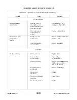
11-87. TROUBLESHOOTING PROCEDURE. The strobe light functions as a condenser discharge system. A
condenser in the power supply is charged to approximately 450 volts dc discharged across the Xenon flash
tube at intervals of approximately 50 flashes per minute. The condenser is parallel across the Xenon flash tube
which is designated to hold off the 450 volts dc applied until the flash tube is triggered by an external pulse.
This pulse is generated by a solid state timing circuit in the power supply.
When troubleshooting the strobe light system, it must first be determined if the trouble is in the flash tube
or the power supply. Replacement of the flash tube will confirm if the tube is defective. A normally operating
power supply will emit an audible tone of 1 to 1.5 kHz. If there is no sound emitted, check the system
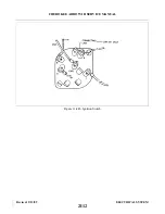
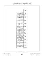
according to the following instructions. When troubleshooting the system, utilize the appropriate schematic at
the back of this section.
a.
Ascertain the input voltage at the power supply is 14 volts.
CAUTION
When disconnecting and connecting the power supply input connections, do
not get the connections reversed. Reversed polarity of the input voltage for
just an instant will permanently damage the power supply. The reversed
polarity destroys a protective diode in the power supply, causing self-
destruction from overheating of the power supply. This damage is
sometimes not immediately apparent, but will cause failure of the system in
time.
b. Check for malfunction in interconnecting cables.
1. Ascertain Pins 1 and 3 of interconnecting cable are not reversed.
2. Using an ohmmeter, check continuity between Pins 1 and 3 of interconnecting cable. If a reading
is obtained on the meter, the cable is shorted and should be replaced.
NOTE
A short of the type described in Steps 1 and 2 will not cause permanent
damage to the power supply, but the system will be inoperative if such a
short exists. Avoid any connection between Pins 1 and 3 o f t h e
interconnecting cable as this will discharge the condenser in the power
supply and destroy the trigger circuits.
CAUTION
When disconnecting the power supply, allow five minutes of bleed down
time prior to handling the unit.
c.
Check interconnecting cables for shorts.
1. Disconnect the output cables from the power supply outlets.
2. The following continuity check can be made with an ohmmeter.
3. Check for continuity between the connectors of each interconnecting cable by checking from Pin 1
to Pin 1, Pin 2 to Pin 2, and Pin 3 to Pin 3. When making these checks if no continuity exists, the
cable is broken and should be replaced.
4. Check continuity between Pins 1 and 2, 1 and 3, 2 and 3 of the interconnecting cable. If continuity
exists between any of these connections, the cable is shorted and should be replaced.
Revised: 2/13/89
2I9
CHEROKEE ARROW III SERVICE MANUAL
ELECTRICAL SYSTEM
Summary of Contents for ARROW III
Page 4: ...THIS PAGE INTENTIONALLY LEFT BLANK 1A4...
Page 12: ...THIS PAGE INTENTIONALLY LEFT BLANK 1A12...
Page 94: ...Figure 4 2 Wing Installation Revised 2 13 89 1D22 CHEROKEE ARROW III SERVICE MANUAL STRUCTURES...
Page 171: ...lH3 INTENTIONALLY LEFT BLANK...
Page 172: ...lH4 INTENTIONALLY LEFT BLANK...
Page 286: ...THIS PAGE INTENTIONALLY LEFT BLANK Revised 2 13 89 2A8...
Page 528: ...INTENTIONALLY LEFT BLANK 2K10 THRU 2L24 2K10...

