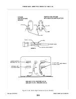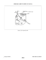
11-88. INSTRUMENT AND PANEL LIGHTS. The instrument and panel lights are broken up into three
groups; Lower Panel Light, Upper Panel Lights, and Compass Light. The instrument lights are controlled by a
5 amp circuit breaker through a transistorized dimmer. A second dimmer control is connected to a variable
resistor which controls the light intensity for all the avionic equipment. The dimmer controls are located in the
middle of the instrument panel just above the pedestal. It may be necessary to gain access to the Dimmer
Control Assembly; if so, follow the instructions given below.
11-89. REMOVAL OF DIMMER CONTROL ASSEMBLY.
a.
Access to the Dimmer Control Assembly is from beneath the instrument panel.
b. Disconnect the electrical connection from the assembly.
c.
Remove the two screws securing the assembly to the instrument panel.
d. Remove assembly from the airplane.
11-90. INSTALLATION OF DIMMER CONTROL ASSEMBLY.
a.
Position the assembly in the instrument panel with the control knobs inserted into their appropriate
slots.
b. Secure the assembly to the instrument panel with the two screws previously removed.
c.
Connect the electrical connection to the assembly.
d. Check operation of Dimmer Control Assembly.
11-91. ANNUNCIATOR PANEL.
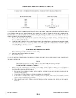
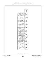
11-92. DESCRIPTION. The annunciator panel is a small cluster of lights which warn of malfunctions in the
various circuits or systems. A malfunction is identified by the illumination of an individual warning light.
There are three warning lights on the PA-28R-201 models and four warning lights on the PA - 2 8 R - 2 0 1 T
models. The PA-28R-201T also has a smaller light which indicates when the auxiliary fuel pump is on. Power
is supplied from the bus bar through a 5 amp fuse located behind the switch panel.
The VAC warning light is controlled by a vacuum sensor switch located at the firewall and is attached to
the vacuum regulator. The sensor switch will activate when the differential pressure is below 3.5 in. Hg.
The OIL warning light is controlled by an oil pressure sensor switch incorporated in the oil line to the oil
pressure gauge and is located at the firewall. The sensor switch will activate when the oil pressure is below 35
psi on PA-28R-201 or 30 psi on PA-28R-201T models.
The ALT warning light is illuminated by current flowing from the bus bar to the alternator circuit. This
condition exists when the alternator is not operating properly and the output is zero. During normal operation,
the alternator warning circuit is also supplied with power from the top diode terminal. This current flows
through a 5 amp fuse, located near the diode heat sink, to the resistor and diode creating a no-flow condition
which does not allow the warning light to light.
The OVER BST warning light used on PA-28R-201T is activated whenever the engine manifold pressure
exceeds 40.75 ± .15 inches of mercury. The manifold pressure sensor is incorporated in the manifold pressure
gauge.
A press-to-test button is used to check the operation of the lights when the engine is running. The lights
will work when the engine is not running with the master switch turned on. The auxiliary fuel on light is not
tested with the press-to-test button.
11-93. REMOVAL OF OIL PRESSURE SENSOR. Access to the sensor unit is gained by reaching up under
the instrument panel. Removal is accomplished by the following.
a.
Disconnect the two electrical leads.
b. Unscrew the sensor unit from the bulkhead fitting.
c.
Catch spillage and cover hole to prevent foreign matter from entering oil line.
Revised: 2/13/89
2I10
CHEROKEE ARROW III SERVICE MANUAL
ELECTRICAL SYSTEM
Summary of Contents for ARROW III
Page 4: ...THIS PAGE INTENTIONALLY LEFT BLANK 1A4...
Page 12: ...THIS PAGE INTENTIONALLY LEFT BLANK 1A12...
Page 94: ...Figure 4 2 Wing Installation Revised 2 13 89 1D22 CHEROKEE ARROW III SERVICE MANUAL STRUCTURES...
Page 171: ...lH3 INTENTIONALLY LEFT BLANK...
Page 172: ...lH4 INTENTIONALLY LEFT BLANK...
Page 286: ...THIS PAGE INTENTIONALLY LEFT BLANK Revised 2 13 89 2A8...
Page 528: ...INTENTIONALLY LEFT BLANK 2K10 THRU 2L24 2K10...

