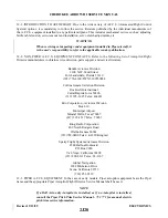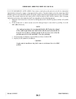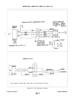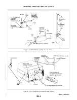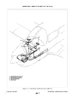
12-9. PILOT’S REMOTE SWITCH. A pilot’s remote switch, located on the left side panel, is provided to
allow the transmitter to be controlled from inside the cabin. The pilot’s remote switch is placarded ON,
AUTO/ARM and OFF/RESET. The switch is normally left in the AUTO/ARM position. The aircraft master
switch must be ON to turn the transmitter OFF. To actuate the transmitter for tests or in the event the automatic
feature was not triggered by impact, move the switch upward to the ON position and leave it in that position as
long as transmission is desired.
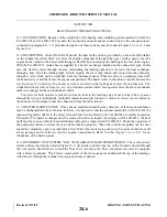
12-10. TESTING EMERGENCY LOCATOR TRANSMITTER. The transmitter operates on the emerg e n c y
frequencies of 121.5 and 243 mHz; both of these frequencies are monitored by the various FAA installations.
Before performing any operational test of the ELT, the following precautions should be observed:
CAUTION
Testing of an ELT should be conducted in a screen room or meter enclosure
to ensure that electromagnetic energy is not radiated during testing. If a
shielded enclosure is not available, testing may be performed in accordance
with the following procedures:
1.
Test should be no longer than three audio sweeps.
2.
If the antenna is removed, a dummy load should be substituted during
the test.
3.
Test should be conducted only within the time period made up of the
first five minutes after any hour.
4.
If the operational tests must be made at a time not included within the
first five minutes after the hour, the test should be coordinated with the
closest FAA Tower or Flight Service Station.
Consult FAA Advisory Circular AC 20-81 for detailed information
concerning above caution.
a.
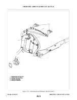
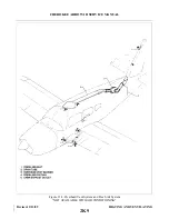
Remove the access plate on the right side of the fuselage aft of sta. 228.30.
b. Tune the aircraft communications receiver to 121.5 mHz and switch the receiver ON; deactivate the
squelch and turn the receiver volume up until a slight background noise is heard.
NOTE
If the aircraft is not fitted with a communications receiver, request that the
tower listen for your test.
c.
On the transmitter, set the ON/ARM/OFF switch to the ON position. Keep the switch in this position
for only a few seconds; then set to the OFF position. Return to the ARM position.
NOTE
The test transmission should have been picked up by the aircraft
communications receiver and/or control tower. During cold weather, there
may be a slight delay before transmission occurs.
Revised: 2/13/89
2J24
CHEROKEE ARROW III SERVICE MANUAL
ELECTRONICS
Summary of Contents for ARROW III
Page 4: ...THIS PAGE INTENTIONALLY LEFT BLANK 1A4...
Page 12: ...THIS PAGE INTENTIONALLY LEFT BLANK 1A12...
Page 94: ...Figure 4 2 Wing Installation Revised 2 13 89 1D22 CHEROKEE ARROW III SERVICE MANUAL STRUCTURES...
Page 171: ...lH3 INTENTIONALLY LEFT BLANK...
Page 172: ...lH4 INTENTIONALLY LEFT BLANK...
Page 286: ...THIS PAGE INTENTIONALLY LEFT BLANK Revised 2 13 89 2A8...
Page 528: ...INTENTIONALLY LEFT BLANK 2K10 THRU 2L24 2K10...

