SECTION XIII
HEATING AND VENTILATING SYSTEM
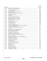
13-1. INTRODUCTION. Because of the simplicity of the heating and ventilating system installed on both the
PA-28R-201 and PA-28R-201T models, the operation and maintenance instructions of the components are
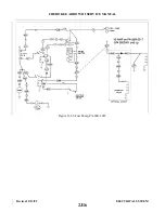
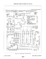
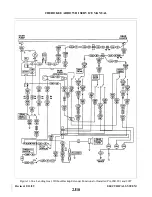
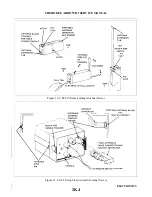
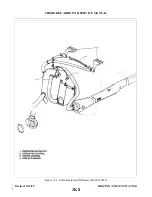
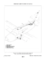
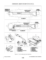
contained in paragraph 13-3. A pictorial description of these systems may be found in Figure 13-1 or 13-2 and
Figure 13-3.
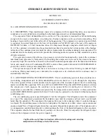
13-2. DESCRIPTION. On the PA-28R-201 model, the heat for the cabin is provided by a hot air muff installed
on the exhaust manifold. Fresh air enters the engine compartment through the nose cowling, passes over the
engine and is vented to the heater muff through a flexible hose located on the baffling at the rear of the engine.
With the PA-28R-201T model, heat is supplied by a hot air exchanger installed on the exhaust tail pipe. In this
case, the fresh air enters through the area surrounding the landing light and is vented to the heat exchanger,
through a hose aft of the landing light. In both models, the air is then heated and vented into the cabin area
through a valve which can be controlled from the instrument panel. When the valve is completely closed off,
the heated air is vented back into the engine compartment. The heater outlet in the cabin is located between the
two front seats. Control for the heater system is located on the right panel below the instruments. The
windshield is kept clear of frost, ice, etc. by a defroster system which also operates from the above mentioned
muff or exchanger but has an individual control.
Fresh air for both models is picked up from an inlet in the leading edge of each wing. The air passes
through the wings to individually controlled outlets located just forward of each seat. An air vent is located in
the bottom of the fuselage to take the exhaust air from the cabin interior.
13-3. HEATER MAINTENANCE. If the exhaust manifold should become defective, carbon monoxide fumes
may be discharged into the cabin area, therefore, it is imperative that the exhaust manifold (on PA-28R-201) be
inspected regularly. (Refer to the latest revision Piper Service Bulletin 691 for Muffler Assembly Inspection
Procedure.) The heater exchanger must be removed in order to inspect the tailpipe on PA-28R-201T, the heat
muff must be removed before the manifold assembly can be inspected on PA-28R-201. Check the operation of
the push-pull controls to ensure the valve doors function properly. When the controls are pulled out, the door
should be completely open to permit full air flow. When the controls are pushed in, the valves should close off
all air passage and vent the air into the engine compartment. Refer to either Figure 13-1 or 13-2 for an
illustration of the heater system.
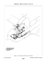
13-4. OVERHEAD VENT SYSTEM. “NOT AVAILABLE WITH AIR CONDITIONING.” The overhead vent
system utilizes the ducting noted in Figure 13-3. Air enters an inlet at the top of the fin and is ducted through
the vent system. Small louvers control the flow of air into the cabin. This vent system may also be equipped
with a blower (optional). This blower, mounted aft of the close-out panel underneath the top of the fuselage,
will force air through the overhead vent system whenever desired.
Revised: 2/13/89
2K6
CHEROKEE ARROW III SERVICE MANUAL
HEATING AND VENTILATING
Summary of Contents for ARROW III
Page 4: ...THIS PAGE INTENTIONALLY LEFT BLANK 1A4...
Page 12: ...THIS PAGE INTENTIONALLY LEFT BLANK 1A12...
Page 94: ...Figure 4 2 Wing Installation Revised 2 13 89 1D22 CHEROKEE ARROW III SERVICE MANUAL STRUCTURES...
Page 171: ...lH3 INTENTIONALLY LEFT BLANK...
Page 172: ...lH4 INTENTIONALLY LEFT BLANK...
Page 286: ...THIS PAGE INTENTIONALLY LEFT BLANK Revised 2 13 89 2A8...
Page 528: ...INTENTIONALLY LEFT BLANK 2K10 THRU 2L24 2K10...

