SECTION XIV
ACCESSORIES AND UTILITIES
PA-28R-201 & PA-28R-201T
14-1. AIR CONDITIONING INSTALLATION.
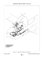
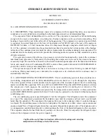
14-2. DESCRIPTION. These installations consist of a compressor with its special bracketry, an evaporator, a
condenser, a receiver-dehydrator, circulating fan, thermal expansion valve, and related plumbing.
The evaporator filters, dehumidifies and cools the air. The evaporator is mounted in a fabricated housing
along with the receiver- d e h y d r a t o r, circulating fan, thermal expansion valve and related plumbing. This
housing is located at the rear of the cabin, aft of the baggage area. The compressor is a piston type unit which
is supported by special bracketry at the front of the engine on PA-28R-201 and at the rear of the engine on
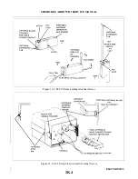
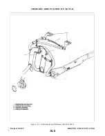
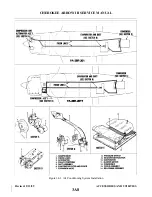
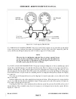
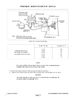
PA28R-201T models. A V-belt connection drives the compressor through a magnetic clutch (refer to Figure
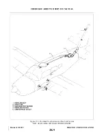
14-1). The condenser is installed on a hinge mounted door that is located on the bottom portion of the fuselage
tail section. The condenser door is mounted to allow extension into the airstream during system operation. The
condenser door is electrically activated to provide the following positions (system on-fully extended or system
off-fully retracted).
The system is protected by a Ranco type pressure switch which automatically controls the condenser
maximum head pressures by temporarily de-clutching the compressor in the event the pressure becomes
excessively high. The controls are located on the aircraft instrument panel adjacent to the heater and defroster
levers, and consist of an Air Conditioning ON-OFF control, a three position fan control (LOW-MED-HIGH) to
govern the cold air velocity, and a temperature control.
The system design is much that there is no increase in drag to the aircraft during its takeoff flight
conditions. During maximum power demands, the compressor is de-clutched and the condenser door is
automatically retracted.
14-3. AIR CONDITIONING SYSTEM OPERATION. The air conditioning system in these airplanes are a
recirculating, independent unit. Its filters dehumidifies and cools the air as it cycles through the evaporator.
The unit is operated from controls mounted on the right side of the instrument panel. The air conditioning
master switch has three positions: FAN only, OFF and AIR COND. When the AIR COND position is selected
the compressor clutch engages, the condenser scoop opens and the circulating fan is turned on. The
temperature is controlled by a thermostat operated by the temperature control selector. A three position fan
switch (LOW-MED-HIGH) operated the blower. The fan may be operated to circulate air without using the air
conditioning unit.
The air conditioning system uses Refrigerant 12 ad the refrigerant. The refrigerant enters the compressor
as a vapor. The compressor pressurized the heat-laden vapor until its pressure and heat reach a point much
hotter than the outside air. The compressor then pumps the vapor to the condenser where it cools and changes
to a liquid. The liquid then passes to the receiver-dehydrator. Its function is to filter, remove any moisture and
ensure a steady flow of liquid refrigerant into the evaporator through the expansion valve. The expansion valve
is a temperature controlled metering valve which regulates the flow of the liquid refrigerant to the evaporator.
The evaporator absorbs the heat from the air passing over the coils. From the evaporator the refrigerant vapor
returns to the compressor where the cycle is repeated.
NOTE
A table at the end of these instructions will assist in locating and correcting
malfunctions which may arise in this system.
Revised: 2/13/89
3A7
CHEROKEE ARROW III SERVICE MANUAL
ACCESSORIES AND UTILITIES
Summary of Contents for ARROW III
Page 4: ...THIS PAGE INTENTIONALLY LEFT BLANK 1A4...
Page 12: ...THIS PAGE INTENTIONALLY LEFT BLANK 1A12...
Page 94: ...Figure 4 2 Wing Installation Revised 2 13 89 1D22 CHEROKEE ARROW III SERVICE MANUAL STRUCTURES...
Page 171: ...lH3 INTENTIONALLY LEFT BLANK...
Page 172: ...lH4 INTENTIONALLY LEFT BLANK...
Page 286: ...THIS PAGE INTENTIONALLY LEFT BLANK Revised 2 13 89 2A8...
Page 528: ...INTENTIONALLY LEFT BLANK 2K10 THRU 2L24 2K10...

