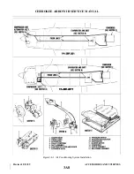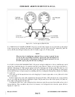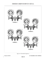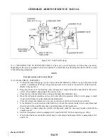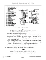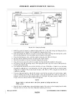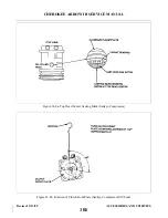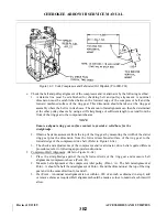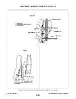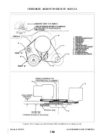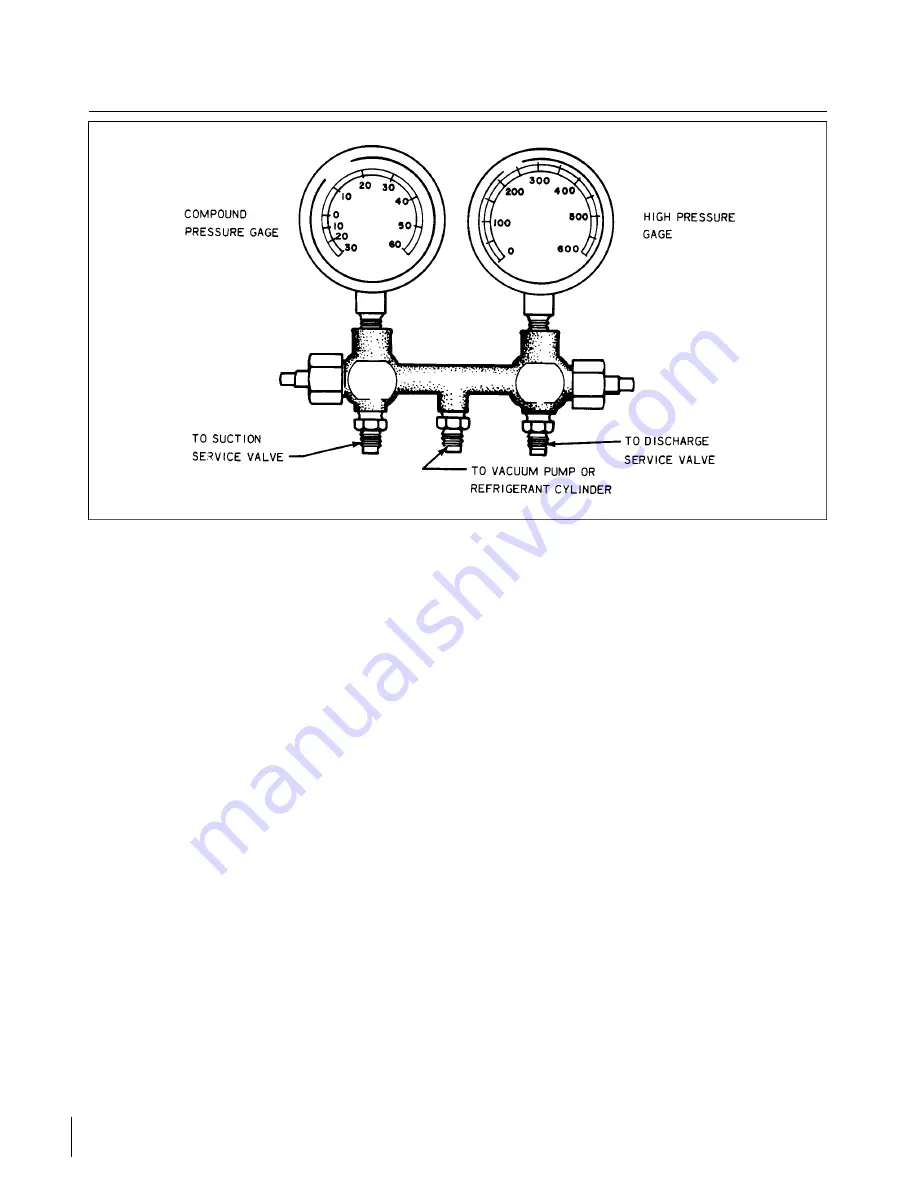
Figure 14-3. Test Gauge and Manifold Set
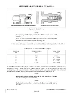
14-7. SERVICE VALVE REPLACEMENT. The valves on the York compressor are sealed with a gasket placed
in the valve port boss. Lubricate the gasket with refrigerant oil of the type used in the compressor, place the
valves with the tube fitting aft and secure with .312 bolts, torque to 15-23 inch pounds.
NOTE
Whenever the air conditioning refrigerant lines or system is opened for any
reason, the lines and fittings should be capped and sealed immediately to
prevent dirt and other contaminants from entering the system. (It is not
advisable to put a plug into the hoses or fittings.)
14-8. TEST GAUGE AND MANIFOLD SET. The proper testing and diagnosis of the air conditioning system
require that a manifold gauge set be attached into the system. This set consists of two gauges mounted to a
manifold. One gauge is a high pressure gauge used in the discharge side of the system. The other is a low
pressure gauge used in the suction side of the system. The manifold is a device having fittings for both gauges
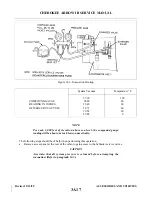
and connection hoses with provisions for controlling the flow of refrigerant through the manifold. See Figures
14-3 and 14-4.
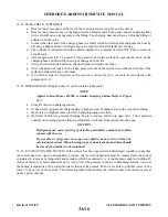
The center port of the manifold set is used for charging or evacuation procedures, or any other service that
may be necessary.
Both the high and low side of the manifold have hand shutoff valves. When the hand valve is turned all the
way in, in a clockwise direction, the manifold is closed. The pressures on the side of the system will, however,
be recorded on the gauge above the hose.
Cracking the hand valve, in the counterclockwise direction, opens the system to the middle service port of
the manifold set. This is desirable only when it is necessary to let refrigerant out or into the system. Refer to
Figures 14-3 and 14-4.
Revised: 2/13/89
3A13
CHEROKEE ARROW III SERVICE MANUAL
ACCESSORIES AND UTILITIES
Summary of Contents for ARROW III
Page 4: ...THIS PAGE INTENTIONALLY LEFT BLANK 1A4...
Page 12: ...THIS PAGE INTENTIONALLY LEFT BLANK 1A12...
Page 94: ...Figure 4 2 Wing Installation Revised 2 13 89 1D22 CHEROKEE ARROW III SERVICE MANUAL STRUCTURES...
Page 171: ...lH3 INTENTIONALLY LEFT BLANK...
Page 172: ...lH4 INTENTIONALLY LEFT BLANK...
Page 286: ...THIS PAGE INTENTIONALLY LEFT BLANK Revised 2 13 89 2A8...
Page 528: ...INTENTIONALLY LEFT BLANK 2K10 THRU 2L24 2K10...

