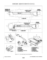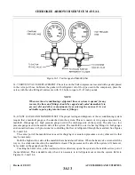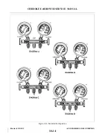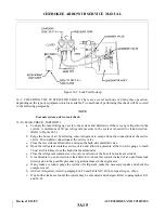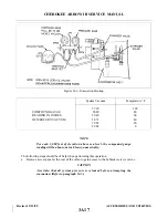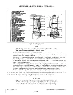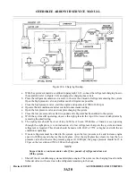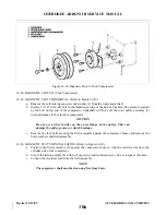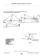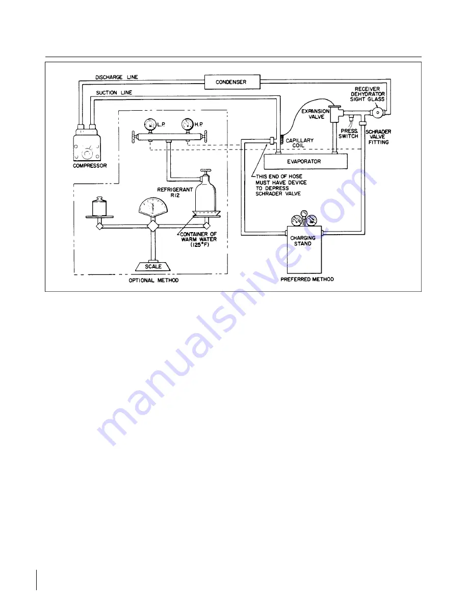
Figure 14-8. Charging Hookup
a.
With the system evacuated as outlined in paragraph 14-13, connect the refrigerant charging hose to
the manifold (refer to Figure 14-8) and purge the charging hose of air.
b. Place the refrigerant container on a scale to observe the amount of refrigerant entering the system.
Open the high pressure valve and add as much refrigerant as possible.
c.
Close the high pressure valve, start the engine and operate it at 900 to 1000 rpm.
d. Operate the air conditioner and set controls to maximum cooling.
e.
Open the low pressure valve and complete charging the system.
f.
Close the low pressure valve after two pounds of refrigerant has been added to the system.
g. With the system still operating, observe the sight glass in the top of the receiver-dehydrator by
removing the plastic plug.
h. The sight glass should be clear of any bubbles or foam. If bubbles or foam are seen passing
through the sight glass, it is an indication of a low refrigerant charge in the system and more
refrigerant is required. This check should be made with OAT of 70°F or higher and with the air
conditioner operating.
i.
If more refrigerant must be added to the system, open the low pressure valve and increase engine
speed to 2000 rpm and observe the sight glass. After the sight glass has cleared, close the low
pressure valve and observe the pressure gauges. At 1000 rpm, the gauge pressure should be 15 to
20 psi on the low side and 150 to 200 on the high side.
NOTE
Suspect leaks or an inaccurate scale if two pounds of refrigerant does not
fill the system.
j.
Shut off the air conditioning system and airplane engine. Then, remove the charging lines from the
Schrader valves with care due to the refrigerant remaining in the hose.
Revised: 2/13/89
3A20
CHEROKEE ARROW III SERVICE MANUAL
ACCESSORIES AND UTILITIES
Summary of Contents for ARROW III
Page 4: ...THIS PAGE INTENTIONALLY LEFT BLANK 1A4...
Page 12: ...THIS PAGE INTENTIONALLY LEFT BLANK 1A12...
Page 94: ...Figure 4 2 Wing Installation Revised 2 13 89 1D22 CHEROKEE ARROW III SERVICE MANUAL STRUCTURES...
Page 171: ...lH3 INTENTIONALLY LEFT BLANK...
Page 172: ...lH4 INTENTIONALLY LEFT BLANK...
Page 286: ...THIS PAGE INTENTIONALLY LEFT BLANK Revised 2 13 89 2A8...
Page 528: ...INTENTIONALLY LEFT BLANK 2K10 THRU 2L24 2K10...

