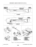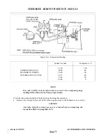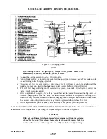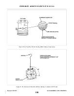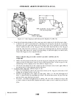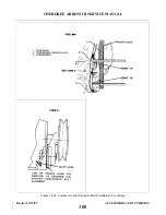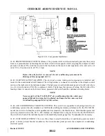
14-19. COMPRESSOR REMOVAL. (The removal of the compressor requires a complete system discharge.)
See paragraph 14-12.
a.
The removal instructions for the York compressor are as follows:
1. Be certain the circuit protector is off for the air conditioning system.
2. Remove the engine cowling and right front baffles.
3. Disconnect the electrical leads to the magnetic clutch on the compressor.
4. Depressurize the air conditioning system.
5. Remove the suction and discharge lines from the service valves on the compressor.
NOTE
All open lines should be capped immediately to prevent dirt and moisture
from entering the system.
6. Loosen the bolt securing the compressor idler pulley to release the belt tension and remove
belt from compressor pulley. (Do not force belt over the pulleys.)
7. Support the compressor and remove the six bolts securing the compressor to the engine
mounting brackets.
b. The removal instructions for the Sankyo compressor are as follows:
1. Ascertain that air conditioning circuit protector is in the off position.
2. Remove engine cowling.
3. Disconnect the electrical leads to the magnetic clutch on the compressor.
4. Depressurize the air conditioning system.
5. Remove the suction and discharge line from the service valves on the compressor.
NOTE
All open lines should be capped immediately to prevent dirt and moisture
from entering the system.
6. Loosen the four bolts securing the compressor in the mounting brackets. Rotate the
compressor in the bracket slots to disconnect drive belt.
7. Support compressor and remove the attachment bolts.
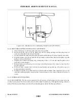
14-20. COMPRESSOR INSTALLATION.
a.
The installation instructions for the York compressor are as follows:
1
Place the compressor to the mounting brackets. Install the six bolts and progressively torque
to 14-17 foot pounds. (Safety all bolts with .032 safety wire.)
2. Check the oil level in the compressor in accordance with instructions given in paragraph
3. Place drive belt over clutch pulley and adjust the alignment of the pulleys and belt in
accordance with instructions given in paragraph 14-22.
CAUTION
Do not force the belt into the pulley sheave. If necessary, remove the idler
assembly.
4. Connect the discharge and suction lines to their respective service valve fittings.
5. Evacuate and charge the system per paragraphs 14-13 and 14-14.
Revised: 2/13/89
3A22
CHEROKEE ARROW III SERVICE MANUAL
ACCESSORIES AND UTILITIES
Summary of Contents for ARROW III
Page 4: ...THIS PAGE INTENTIONALLY LEFT BLANK 1A4...
Page 12: ...THIS PAGE INTENTIONALLY LEFT BLANK 1A12...
Page 94: ...Figure 4 2 Wing Installation Revised 2 13 89 1D22 CHEROKEE ARROW III SERVICE MANUAL STRUCTURES...
Page 171: ...lH3 INTENTIONALLY LEFT BLANK...
Page 172: ...lH4 INTENTIONALLY LEFT BLANK...
Page 286: ...THIS PAGE INTENTIONALLY LEFT BLANK Revised 2 13 89 2A8...
Page 528: ...INTENTIONALLY LEFT BLANK 2K10 THRU 2L24 2K10...

