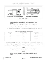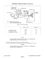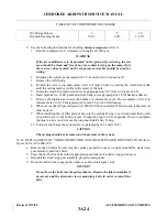
TABLE XIV-III. COMPRESSOR OIL CHARGE
Oil Charge Ounces
6
8
10
Dipstick Reading Inches
13/16”
1.00”
1-3/16”
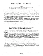
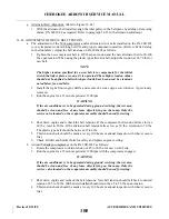
b. Use the following instructions for checking Sankyo compressor oil level.
1. Run the compressor for 10 minutes with engine at 1900 rpm.
WARNING
If the air conditioner is to be operated on the ground for servicing, the test
area should be clean and free of any loose objects lying on the ramp. Only
the service valves located on the evaporator assembly should be used for
testing.
2. Discharge the system per paragraph 14-12; be careful not to loose any oil.
3. Remove the oil fill plug.
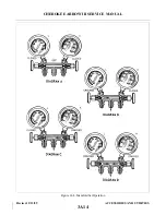
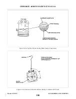
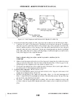
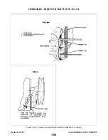
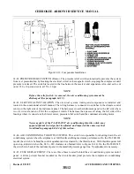
4. Position the rotor to top dead center (refer to Figure 14-8a) by rotating the clutch front plate
until the casting mark is visible in the center of the hole.
5. Rotate the clutch front plate clockwise by approximately 110° (refer to Figure 14-8b).
6. Insert dipstick No. 32447 purchased from Sankyo (see paragraph 14-18 for Sankyo address).
7. Remove the dipstick and count the number of increments of oil. The acceptable oil level in
increments is 7 to 10. This represents between 2.6 and 4.4 fluid ounces.
8. When oil is added, Piper refrigerant oil PMS-L2000 or equivalent 500 viscosity refrigerant oil
must be used.
9. When installing the oil filler plug, make sure the sealing O-ring is not twisted and that no dirt
nor particles are on the O-ring or seat. Torque the plug to 6-9 foot-pounds. Do not overtighten
the plug to stop a leak; remove the plug and install a new O-ring.
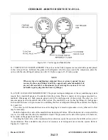
10. Evacuate and charge the system (refer to paragraphs 14-13 and 14-14).
CAUTION
The oil plug should not be removed with pressure in the system.
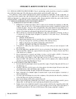
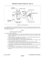
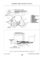
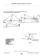
14-22. REPLACEMENT OF YORK COMPRESSOR AND/OR ALT E R N ATOR DRIVE BELTS. (Refer to
Figure 14-9a.) (PA-28R-201)
a.
Remove the old belts by removing the spinner, propeller, nose cowl, right front baffle, starter ring
gear assembly and drive belts.
b. Place the new belt or belts in their appropriate positions on the starter ring gear sheaves.
c.
Reinstall the starter ring gear assembly, propeller and spinner.
d. Route the belts to the proper pulley sheaves as shown in Figure 14-9a.
CAUTION
Do not force the belts into the pulley sheaves. Remove the idles assemblies if
necessary and the alternator lower mounting bolts in order to install the
belts.
Revised: 2/13/89
3A24
CHEROKEE ARROW III SERVICE MANUAL
ACCESSORIES AND UTILITIES
Summary of Contents for ARROW III
Page 4: ...THIS PAGE INTENTIONALLY LEFT BLANK 1A4...
Page 12: ...THIS PAGE INTENTIONALLY LEFT BLANK 1A12...
Page 94: ...Figure 4 2 Wing Installation Revised 2 13 89 1D22 CHEROKEE ARROW III SERVICE MANUAL STRUCTURES...
Page 171: ...lH3 INTENTIONALLY LEFT BLANK...
Page 172: ...lH4 INTENTIONALLY LEFT BLANK...
Page 286: ...THIS PAGE INTENTIONALLY LEFT BLANK Revised 2 13 89 2A8...
Page 528: ...INTENTIONALLY LEFT BLANK 2K10 THRU 2L24 2K10...

