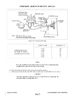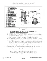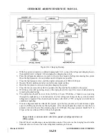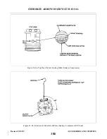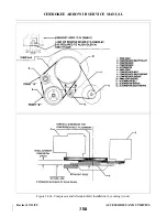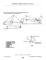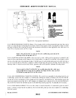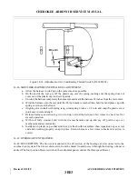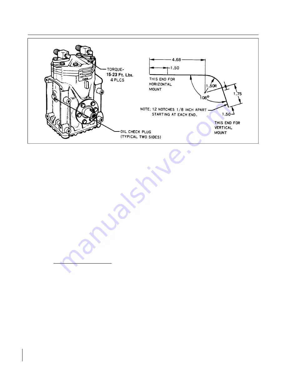
Figure 14-9. York Compressor and Fabricated Oil Dipstick (PA-28R-201)
e.
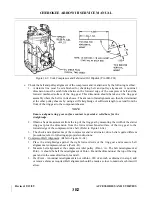
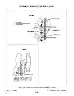
Check the belt and pulley alignment of the compressor and/or alternator by the following method:
1. A daturm line must be established for checking belt and pulley alignment. A nominal
dimension must be established between the forward edge of the compressor belt and the
forward machined surface of the ring gear. This dimension should be taken at the ring gear
assembly where the belt is in its sheave. The amount of misalignment can then be determined
at the other pulley sheaves by using a stiff straightedge of sufficient length to extend from the
front of the ring gear to the component sheaves.
NOTE
Ensure adequate ring gear surface contact to provide a solid base for the
straightedge.
2. Obtain a basic measurement from the top of the ring gear by measuring the width of the starter
ring gear plus the dimension from the forward machined surface of the ring gear to the
forward edge of the compressor drive belt. (Refer to Figure 14-9a.)
3. The check and adjustments of the compressor and/or alternator drive belts require diff e r e n t
procedures; refer to following appropriate instructions:
f.
Compressor Belt Alignment: (Refer to Figure 14-9a.)
1. Place the straightedge against the right forward side of the ring gear and measure belt
alignment at compressor sheave (Point - B).
2. Measure belt alignment at the compressor idler pulley (Point - A). The belt misalignment at
Point - A should be half the misalignment of Point - B and the dimension at the top of the ring
gear and in the same direction fore and aft.
3. If at Point - A nominal misalignment is not within ±.030 of an inch as obtained in step 2, add
or remove shims as required. Belt alignment should be made as close to nominal as shims will
allow.
Revised: 2/13/89
3B2
CHEROKEE ARROW III SERVICE MANUAL
ACCESSORIES AND UTILITIES
Summary of Contents for ARROW III
Page 4: ...THIS PAGE INTENTIONALLY LEFT BLANK 1A4...
Page 12: ...THIS PAGE INTENTIONALLY LEFT BLANK 1A12...
Page 94: ...Figure 4 2 Wing Installation Revised 2 13 89 1D22 CHEROKEE ARROW III SERVICE MANUAL STRUCTURES...
Page 171: ...lH3 INTENTIONALLY LEFT BLANK...
Page 172: ...lH4 INTENTIONALLY LEFT BLANK...
Page 286: ...THIS PAGE INTENTIONALLY LEFT BLANK Revised 2 13 89 2A8...
Page 528: ...INTENTIONALLY LEFT BLANK 2K10 THRU 2L24 2K10...

