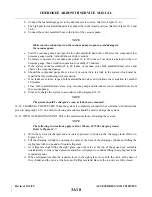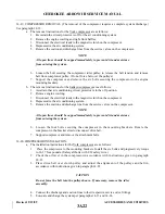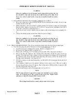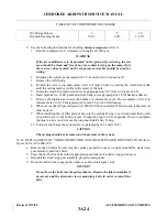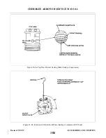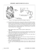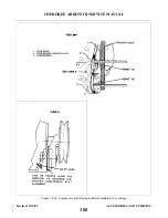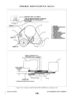
14-31. CONDENSER. The condenser is mounted in a frame assembly located in the bottom of the fuselage
between stations 156.00 and 191.00.
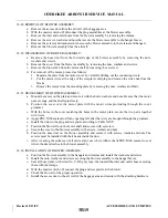
14-32. CONDENSER ASSEMBLY REMOVAL.
a.
Discharge the system. (See paragraphs 14-5 and 14-12.)
b. Remove access panel from the aft bulkhead of cabin.
c.
Remove the forward cover panel.
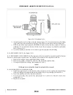
d. Uncouple the suction and discharge hoses at the condenser fitting. (See paragraph 14-5, B-7).
Remove the hose clamps holding the hoses to the condenser frame.
e.
Remove the AN-3 bolts from the upper ends of the side hinges and rod ends.
f.
Support the condenser assembly and remove the bolt attaching the actuating rod to the condenser
assembly.
g. Lower the aft end of the assembly on the piano hinge at the forward end of assembly.
h. Remove the eight screws attaching the piano hinge to the condenser frame assembly and remove
from aircraft.
i.
To remove condenser core from assembly, remove the screws in the side mounting frame.
14-33. CONDENSER INSTALLATION.
a.
Install the condenser core to the frame assembly with the hose fitting forward and up.
b. Place the condenser and frame assembly to the fuselage frame mounting bracket and insert the (8)
screws into the piano hinge.
c.
Attach the side hinges and actuating rod and rig per paragraph 14-35.
d. Seal and couple the hose fittings (seal with Loctite refrigerant sealant applied to flanges only).
e.
Adjust the condenser in accordance with paragraph 14-35.
f.
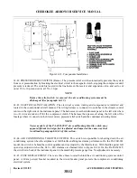
Seal all around cover panel (and aft cover panel if removed) with Permagum Bead No. 576
purchased from Prestolite Engineering Company. (See Figure 14-11.)
WARNING
Whenever it is necessary to remove and replace the cabin rear panel, it
should be replaced and sealed in the original manner to prevent exhaust
gases from entering the cabin. After removing and replacing the rear panel,
conduct a carbon monoxide test on ground and in flight with or without the
air conditioner operating. Presence of CO2 shall not exceed 1 part in
20,000.
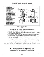
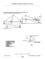
14-34. CONDENSER DOOR ACTUATOR. The actuator is on a bracket mounted between two bulkheads in
the tail cone. It is coupled to the condenser assembly through a bellcrank mounted to a bracket on the bulkhead
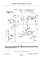
aft of the condenser. The actuator travel is controlled by two limit switches. Both the up and down switches are
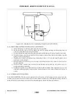
located on the actuator. Refer to Figure 14-11 for the switch locations.
14-35. CONDENSER ASSEMBLY RIGGING INSTRUCTIONS. (Refer to Figure 14-11.) The condenser
assembly is actuated by an electric motor through bellcranks, push rods and limit switches.
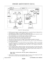
It is necessary for the condenser door to fit flush with the fuselage skin and with increased force along the
forward edge. The following steps will help accomplish this requirement: (Refer to Figure 14-11.)
a.
Adjust open limit switch (5) to open the condenser door (8) five inches when measured from the
leading edge of the door to the fuselage skin.
Revised: 2/13/89
3B8
CHEROKEE ARROW III SERVICE MANUAL
ACCESSORIES AND UTILITIES
Summary of Contents for ARROW III
Page 4: ...THIS PAGE INTENTIONALLY LEFT BLANK 1A4...
Page 12: ...THIS PAGE INTENTIONALLY LEFT BLANK 1A12...
Page 94: ...Figure 4 2 Wing Installation Revised 2 13 89 1D22 CHEROKEE ARROW III SERVICE MANUAL STRUCTURES...
Page 171: ...lH3 INTENTIONALLY LEFT BLANK...
Page 172: ...lH4 INTENTIONALLY LEFT BLANK...
Page 286: ...THIS PAGE INTENTIONALLY LEFT BLANK Revised 2 13 89 2A8...
Page 528: ...INTENTIONALLY LEFT BLANK 2K10 THRU 2L24 2K10...

