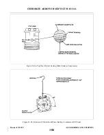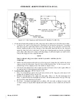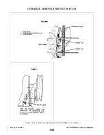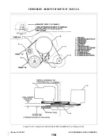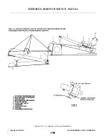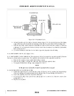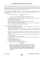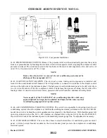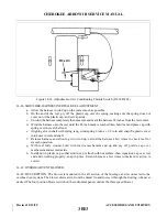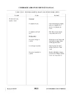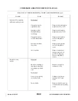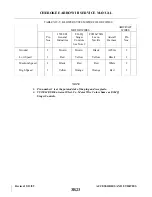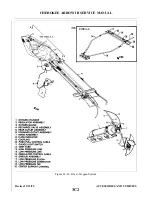
14-39. EVA P O R ATOR ASSEMBLY. The evaporator assembly consists of the evaporator core, receiver
d e h y d r a t o r, expansion valve, circulating fan and pressure switch together with necessary housing and
plumbing. The housing is fabricated of Cycolac type material. The condensed moisture is dumped over board
through a hose clamped to a fitting on the bottom of the evaporator housing.
14-40. EVAPORATOR ASSEMBLY REMOVAL. The evaporator assembly is located behind the cabin rear
panel, attached to the mounting panel with 12 screws and washers, and a bracket securing the back to the
mounting panel.
a.
Remove air conditioning filter cover, filter and rear access panels.
NOTE
Discharge the system before disassembling. (Refer to paragraph 14-12.)
b. Uncouple the liquid line from the inlet side of the receiver-dehydrator and the suction line from the
evaporator core outlet. (See paragraph 14-5, B-7.)
c.
Disconnect the related electrical wires.
d. Remove flexible air duct from housing outlet. Remove drain hose from housing.
e.
Remove temperature probe from evaporator housing.
f.
Remove the screws attaching the support bracket and evaporator housing to the mounting panel.
Remove the assembly through the access hole in the bulkhead.
14-41. EVAPORATOR ASSEMBLY INSTALLATION.
a.
Cement gasket in place on the flanges of the evaporator housing and attach the large end of the
mounting gasket to the back of the housing.
b. Install the housing through the access hole with the air duct outlet on top. Mate the mounting
flanges to the mating surface of the mounting panel and insert the screws. (Do not tighten at this
time.)
c.
Line up the mounting bracket with mating holes in mounting panel, insert screws and tighten.
Tighten screws in the flange at this time. Be certain gasket is in place. The flange must have an air
tight seal.
d. Couple the suction and discharge lines to their respective fittings (apply Loctite refrigerant sealant
to tube flanges only).
e.
Evacuate and charge system. (See paragraphs 14-13.)
f.
Check for leaks (see paragraph 14-9) if no leaks are detected. Seal and install access panel on
evaporator housing.
g. Couple flexible air duct and drain tube.
h. Make and check electrical connections.
i.
Check operation of blower and refrigerant systems.
j.
Install rear bulkhead panels. Be certain to seal. (See NOTE.)
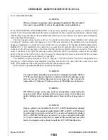
WARNING
Whenever it is necessary to remove and replace the cabin rear panel, it
should be replaced and sealed in the original manner to prevent exhaust
gases from entering the cabin. After removing and replacing the rear panel,
conduct a carbon monoxide test on the ground and in flight with and
without the air conditioner operating. Presence of CO shall not exceed 1
part in 20,000.
Revised: 2/13/89
3B11
CHEROKEE ARROW III SERVICE MANUAL
ACCESSORIES AND UTILITIES
Summary of Contents for ARROW III
Page 4: ...THIS PAGE INTENTIONALLY LEFT BLANK 1A4...
Page 12: ...THIS PAGE INTENTIONALLY LEFT BLANK 1A12...
Page 94: ...Figure 4 2 Wing Installation Revised 2 13 89 1D22 CHEROKEE ARROW III SERVICE MANUAL STRUCTURES...
Page 171: ...lH3 INTENTIONALLY LEFT BLANK...
Page 172: ...lH4 INTENTIONALLY LEFT BLANK...
Page 286: ...THIS PAGE INTENTIONALLY LEFT BLANK Revised 2 13 89 2A8...
Page 528: ...INTENTIONALLY LEFT BLANK 2K10 THRU 2L24 2K10...

