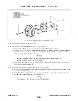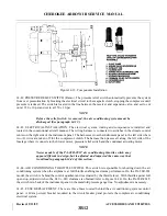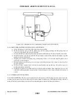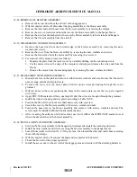
14-49. REMOVAL OF BLOWER ASSEMBLY.
a.
Remove the access door from the aft wall of the baggage area.
b. With the master switch off, disconnect the plug assemblies at the blower assembly.
c.
Remove the inlet and outlet hoses from the blower assembly by removing the clamps.
d. Remove the screws, washers and nuts that secure the blower assembly to the hangar braces.
e.
Remove the screws and washers which secure the blower assembly to the retainer and hangars.
f.
Remove the blower assembly from the aircraft.
14-50. DISASSEMBLY OF BLOWER ASSEMBLY.
a.
Remove the hose duct from the forward edge of the blower assembly by removing the nuts,
washers and screws.
b. Remove the cover from the blower assembly by removing the nuts, washers and screws.
c.
Remove the blower fan from the motor shaft by removing the set screw.
d. For removal of the motor, proceed as follows:
1. Separate the plate from the motor cover by carefully drilling out the connecting rivets.
2. Cut the motor wires at the edge of the receptacle and plug and remove the wire ends from the
blocks.
3. Remove the motor from the mounting plate by removing the nuts, washers and bolts.
14-51. REASSEMBLY OF BLOWER ASSEMBLY.
a.
Mount the motor on the plate and secure it with the bolts, washers and nuts. Be sure that the motor
nuts are snug and the shaft spins freely.
b. Position the cover over the motor plate with the motor wires protruding through the cover
grommet.
c.
With the holes in the cover matching the holes in the motor plate, secure the two parts together
with rivets.
d. Apply PRC-5000 sealant to fill any opening left after the wires are brought through the grommet.
e.
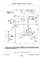
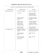
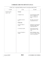
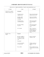
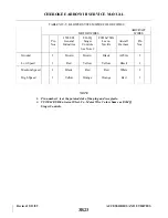
Install the wires in the plug and receptacle according to Table XIV-V.
f.
Position the blower fin on the motor shaft and secure with set screw.
g. Secure the cover to the blower assembly with screws, washers and nuts.
h. Position the hose duct on the blower assembly and secure it with screws, washers and nuts. The
screws must be installed with their heads inside the duct.
i.
After cleaning the surfaces of all old sealant, use white rubber chalk PRC-5000 sealant to seal
where the duct attaches to the blower assembly.
14-52. INSTALLATION OF BLOWER ASSEMBLY.
a.
Position the blower assembly in the hangars and retainer and install the washers and screws.
b. Install the nuts, washers and screws securing the blower assembly to the hangar braces.
c.
Seal all hose joints with Arno No. C-520 gray tape; then install the inlet and outlet hoses securing
them with the clamps.
d. With the master switch off, connect the plug and receptacles at the blower.
e.
Check the blower for the proper operation.
f.
Install the access door to the aft wall of the baggage area and secure with the attaching hardware.
Revised: 2/13/89
3B15
CHEROKEE ARROW III SERVICE MANUAL
ACCESSORIES AND UTILITIES
Summary of Contents for ARROW III
Page 4: ...THIS PAGE INTENTIONALLY LEFT BLANK 1A4...
Page 12: ...THIS PAGE INTENTIONALLY LEFT BLANK 1A12...
Page 94: ...Figure 4 2 Wing Installation Revised 2 13 89 1D22 CHEROKEE ARROW III SERVICE MANUAL STRUCTURES...
Page 171: ...lH3 INTENTIONALLY LEFT BLANK...
Page 172: ...lH4 INTENTIONALLY LEFT BLANK...
Page 286: ...THIS PAGE INTENTIONALLY LEFT BLANK Revised 2 13 89 2A8...
Page 528: ...INTENTIONALLY LEFT BLANK 2K10 THRU 2L24 2K10...

