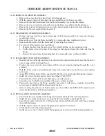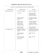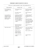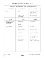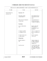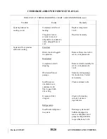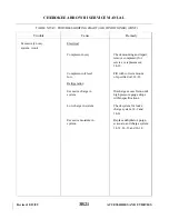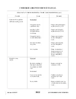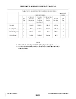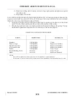
14-55. TROUBLESHOOTING. (Refer to Table XIV-VI)
14-56. FIXED OXYGEN SYSTEM.
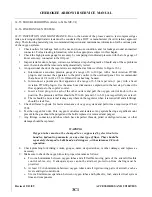
14-57. INSPECTION AND MAINTENANCE. Due to the nature of the process used to test compressed gas
tanks, servicing and hydrostatic tests must be conducted by a DOT or manufacturer (Scott Aviation) approved
shop. The following material gives recommended inspection and maintenance information for the various parts
of the oxygen systems.
1. Check outlets for leakage both in the use and non-use condition, and for leakage around an inserted
connector. For leak testing information, refer to the appropriate subject in this chapter.
2. Check the high pressure gauge for accuracy by comparing its indicated pressure with that of a gauge of
know accuracy, connected to the fill port.
3. Inspect tank for dents, bulges, corrosion, and major strap chafing marks. Should any of these problems
exist, the tank should be removed and hydrostatically tested.
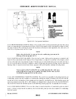
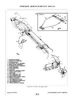
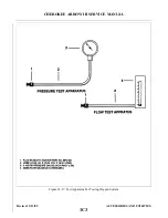
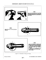
4. An operational check of the regulator is accomplished as follows: (Refer to Figure 35-3.)
a.
Interconnect a sensitive pressure gauge of a range of 0 to 100 psi, with a Scott Aviation 857000
plug-in, and connect the apparatus to the pilot’s outlet in the overhead panel. It is recommended
that a hose of 1/4 in. ID x 1/2 in. OD and 18 inches long be used.
b. Interconnect a pneumatic flow apparatus of a range of 0-5 liters per min (1 pm.) with a Scott
Aviation 8570-00 plug-in. Use the same hose dimension as explained in the last step. Connect the
flow apparatus to the copilot’s outlet.
c.
Insert a Scott plug-in in each of the other outlets and pull the oxygen control knob to the on
position. The pressure and flow should be 55 to 80 psi and 3.3 to 5.31 pm. respectfully at sea level.
d. There should be no external leakage anywhere on the regulator when it is turned off and all fittings
should be leak free.
5. Check airframe logbook for last maintenance of oxygen system and perform as required per Chart
3502.
6. Test the oxygen for odor. Pure oxygen is odorless and tasteless. Any system having a significant odor
present in the gas should be purged and the bottle replaced or removed and purged.
7. Any fittings, connector, and tubes which have imperfect threads, pitted or disfigured cones, or other
damage should be replaced.
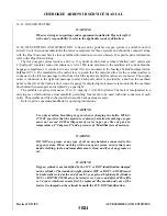
WARNING
Oxygen tubes must not be clamped to or supported by electrical wire
bundles, hydraulic, pneumatic, or any other type of lines. They should be
separately clamped to bulkhead and stringers, with minimum 1/8 inch
separation.
8. Check plumbing for kinking, cracks, gouges, dents, deep scratches, or other damage, and replace as
necessary.
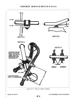
9. Make sure to check the oxygen lines for proper clearance as follows:
a.
Two inch minimum between oxygen tubes and all flexible moving parts of the aircraft (flexible
control cables, etc). It adequate space cannot be attained, protection from chafing must be
provided.
b. At least 1/2 inch minimum between oxygen tubes and all rigid moving parts of aircraft, such as
levers and rigid control rods.
c.
Six inch minimum separation between oxygen tubes and hydraulic, fuel, and electrical system
lines and components.
Revised: 2/13/89
3C1
CHEROKEE ARROW III SERVICE MANUAL
ACCESSORIES AND UTILITIES
Summary of Contents for ARROW III
Page 4: ...THIS PAGE INTENTIONALLY LEFT BLANK 1A4...
Page 12: ...THIS PAGE INTENTIONALLY LEFT BLANK 1A12...
Page 94: ...Figure 4 2 Wing Installation Revised 2 13 89 1D22 CHEROKEE ARROW III SERVICE MANUAL STRUCTURES...
Page 171: ...lH3 INTENTIONALLY LEFT BLANK...
Page 172: ...lH4 INTENTIONALLY LEFT BLANK...
Page 286: ...THIS PAGE INTENTIONALLY LEFT BLANK Revised 2 13 89 2A8...
Page 528: ...INTENTIONALLY LEFT BLANK 2K10 THRU 2L24 2K10...

