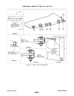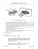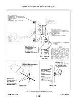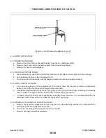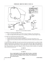
4-12. INSTALLATION OF WING FLAP. (Refer to Figure 4-1.)
a.
Replace the wing flap by placing the flap onto its proper position and inserting the hinge bolts,
bushings, washers, and nuts.
b. With the flap control in the full flap position, place the bushing on the outboard side of the rod end
bearing and insert and tighten the bolt.
c.
Operate the flap several times to be certain it is operating freely.
4-13. WING.
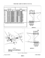
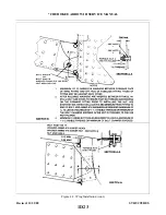
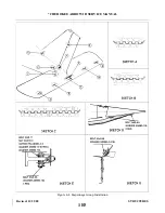
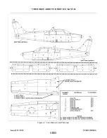
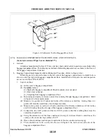
4-14. REMOVAL OF WING. (Refer to Figure 4-2.)
a.
b. Drain the brake lines and reservoir. (Refer to Draining Brake System, Section II.)
c.
Drain the hydraulic lines of the landing gear of the wing to be removed by separating the lines and
elbows at the actuating cylinder.
d. Remove the access plate at the wing butt rib and wing inspection panels. (Refer to Access Plates and
e.
Remove the front and back seats from the airplane.
f.
Expose the spar box and remove the side trim cockpit panel assembly that corresponds with the wing
being removed.
g. Place the airplane on jacks. (Refer to Jacking, Section II.)
NOTE
To help facilitate reinstallation of control cables, and fuel and hydraulic
lines, mark cable and line ends in some identifying manner and attach a
line where applicable to cables before drawing them through the fuselage or
wing.
h. Disconnect the aileron balance and control cables at the turnbuckles that are located within the
fuselage aft of the spar.
i.
If the left wing is being removed, remove the cotter pin from the pulley bracket assembly to allow the
left aileron balance cable end to pass between the pulley and bracket.
j.
Disconnect the flap from the torque tube by extending the flap to its fullest degree, and removing the
bolt and bushing from the bearing at the aft end of the control rod.
k. Disconnect the fuel line at the fitting located inside of the wing, by removing the access panel on the
forward inboard portion of the wheel well and reaching through to the fuel line coupling.
CAUTION
To prevent damage or contamination of fuel, hydraulic and miscellaneous
lines, place a protective cover over the line fittings and ends.
1. Remove the clamps that are necessary to release the electrical harness assembly. Disconnect the leads
from the terminal strip by removing the cover, and appropriate nuts and washers.
m. With the appropriate trim panel removed, disconnect the hydraulic brake line at the fitting located
within the cockpit at the leading edge of the wing.
n. Disconnect the landing gear hydraulic lines at the fittings aft of the spar and within the fuselage.
Issued: 12/15/76
1D24
* CHEROKEE ARROW III SERVICE MANUAL
STRUCTURES
Summary of Contents for ARROW III
Page 4: ...THIS PAGE INTENTIONALLY LEFT BLANK 1A4...
Page 12: ...THIS PAGE INTENTIONALLY LEFT BLANK 1A12...
Page 94: ...Figure 4 2 Wing Installation Revised 2 13 89 1D22 CHEROKEE ARROW III SERVICE MANUAL STRUCTURES...
Page 171: ...lH3 INTENTIONALLY LEFT BLANK...
Page 172: ...lH4 INTENTIONALLY LEFT BLANK...
Page 286: ...THIS PAGE INTENTIONALLY LEFT BLANK Revised 2 13 89 2A8...
Page 528: ...INTENTIONALLY LEFT BLANK 2K10 THRU 2L24 2K10...

