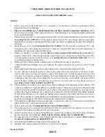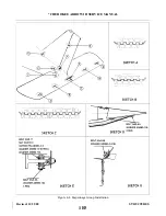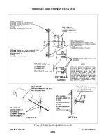
a. Remove the screws from around the upper and lower tail cone fairing assembly and remove the fairing
separately.
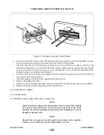
b. Block the trim cable at the barrel of the trim screw assembly to prevent the cable from unwrapping.
c.
Remove the access panel to the aft section of the fuselage located at the back wall of the baggage
compartment.
pulleys forward of the cable turnbuckles to prevent the forward cable form unwrapping.
e.
Disconnect the trim cables at the turnbuckles within the aft section of the fuselage.
f.
Relieve tension from the stabilator control cables by loosening one of the cable turnbuckles in the aft
section of the fuselage.
g. Disconnect the stabilator control cables from the stabilator balance arm by removing cotter pins, nuts,
washers, bushings and clevis bolts.
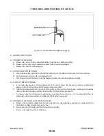
h. Disconnect the trim assembly from the aft bulkhead of the fuselage by removing the attaching nuts,
washers and bolts of the horizontal and diagonal support brackets.
i.
Move the trim assembly up through the tail cone fairing cutout in the stabilator and remove, with
cable, from the airplane.
j.
Remove the stabilator by disconnecting the stabilator at its hinge points.
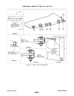
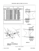
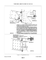
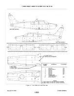
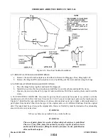
4-19. INSTALLATION OF STABILATOR. (Refer to Figure 4-4.)
CAUTION
Comply with latest revision of Piper Service Bulletin 856.
NOTE
A clearance of .25 +/- .06 of an inch between the stabilator and the side of
the fuselage and .18 of an inch minimum between all parts of the stabilator
and the tail cone assembly must be maintained throughout the stabilator
travel. Use a proper washer combination on the stabilator hinges to attain
the necessary tolerances.
a.
Insert the stabilator in position and install attaching hinge bolts, washers and nuts.
b. Move the trim assembly through the cutout in the stabilator and attach the brackets of the assembly to
the aft bulkhead with bolts, washers and nuts. Insert the trim cable ends into the fuselage.
c.
Attach the stabilator control cables to the stabilator balance arm with clevis bolts, bushings, washers,
nuts and cotter pins.
d. Connect the ends of the fore and aft trim cables at the turnbuckles within the aft section of the
fuselage.
e.
Remove the cable block from the trim control cable within the fuselage.
f.
g. Remove the cable blocks from the trim cable at the barrel of the trim screw assembly.
h. Set stabilator trim control cable tension and check rigging and adjustment according to Rigging and
Adjustment of Stabilator Trim, Section V.
i.
Remove the pad from the aft section of the fuselage and replace the access panel.
j.
Install the tail cone fairing and remove tail stand.
Revised: 2/13/89
1E3
* CHEROKEE ARROW III SERVICE MANUAL
STRUCTURES
Summary of Contents for ARROW III
Page 4: ...THIS PAGE INTENTIONALLY LEFT BLANK 1A4...
Page 12: ...THIS PAGE INTENTIONALLY LEFT BLANK 1A12...
Page 94: ...Figure 4 2 Wing Installation Revised 2 13 89 1D22 CHEROKEE ARROW III SERVICE MANUAL STRUCTURES...
Page 171: ...lH3 INTENTIONALLY LEFT BLANK...
Page 172: ...lH4 INTENTIONALLY LEFT BLANK...
Page 286: ...THIS PAGE INTENTIONALLY LEFT BLANK Revised 2 13 89 2A8...
Page 528: ...INTENTIONALLY LEFT BLANK 2K10 THRU 2L24 2K10...

