Stage 32
High rate
Low rate
ELEVATOR 1/3 “ ( 10mm) up
1/5” ( 6mm) up
1/3 “ ( 10mm) down
1/5” ( 6mm) down
RUDDER 1 “ (25mm) right
5/8” (16mm) right
1” (25mm) left
5/8” (16mm) left
AILERON 1/2” (16mm) up
1/3” (10mm) up
1/2” (16mm) down
1/3” (10mm) down.
Note: If your radio does not have dual rates, then set the control surfaces to the low rates.
19
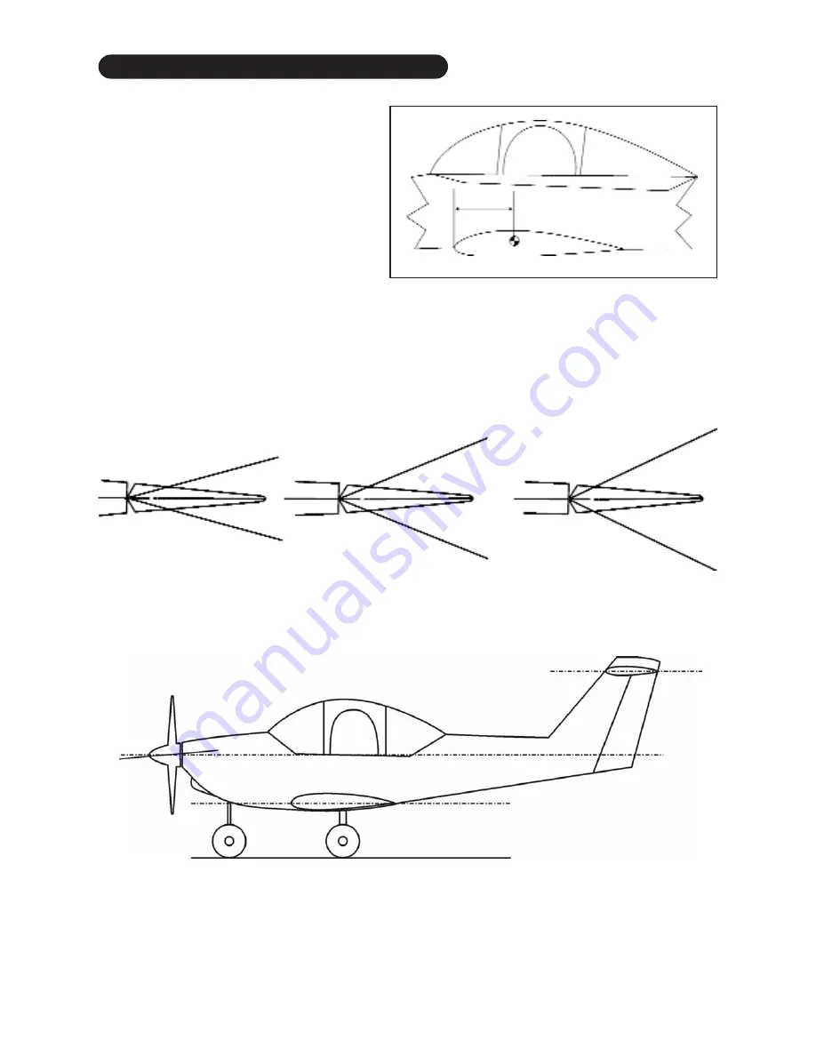
65 mm
2.56”
Elevator
Aileron
Rudder
5/8”
16mm
5/8”
16mm
1/3”
10mm
1/3”
10mm
1/5”
6mm
1/5”
6mm
CG
NOTE
: The throws are measured at the
widest part of the elevator, rudder and aileron.
Adjust the position of the pushrods at the con-
trol/servo horns to control the amount of
throw. You may also use the ATV’s if your
transmitter has them but the mechanical link-
ages should still be set so that the ATV’s are
near 100% for best servo resolution.
CG, INCIDENCE & THROW SPECIFICATIONS
engine .0. To 2
degrees down thrust
Horizontal stabilizer
incidence 0 degrees
Wing - incidence 0 degrees


