background image

SECTION 5


PIPER AIRCRAFT CORPORATION

PERFORMANCE


PA-28-236, DAKOTA

REPORT: VB-910


ISSUED: JUNE 1, 1978 


5-18


REVISED: AUGUST 27, 1979

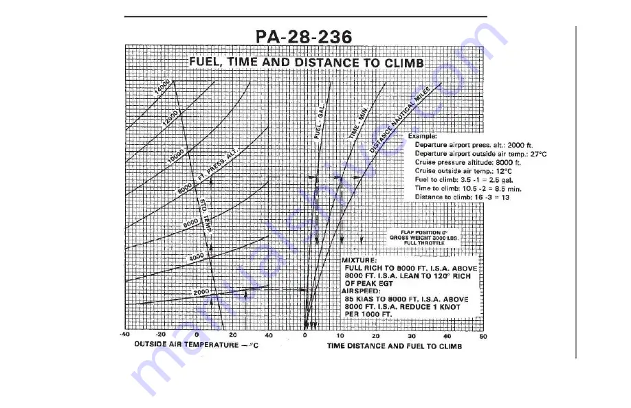
FUEL, TIME AND DISTANCE TO CLIMB

Figure 5-15

Summary of Contents for PA-28-236 DAKOTA

Page 1: ......

Page 2: ...L D O A NO SO 1 JUNE 1 1978 PIPER AIRCRAFT CORPORATION VERO BEACH FLORIDA FAA APPROVED IN NORMAL CATEGORY BASED ON CAR 3 THIS HANDBOOK INCLUDES THE MATERIAL REQUIRED TO BE FURNISHED TO THE PILOT BY CA...

Page 3: ...HIS HANDBOOK TO APPLICABLE AIRCRAFT THIS HAND BOOK IS VALID FOR USE WITH THE AIRPLANE IDENTIFIED ON THE FACE OF THE TITLE PAGE SUBSEQUENT REVISIONS SUPPLIED BY PIPER AIRCRAFT CORPORATION MUST BE PROPE...

Page 4: ......

Page 5: ...REPORT VB 910 ISSUED JUNE 1 1978 b...

Page 6: ...rmation necessary to update the text of the present handbook and or to add information to cover added airplane equipment I Revisions Revisions will be distributed whenever necessary as complete page r...

Page 7: ...n spelling punctuation or the physical location of material on a page will not be identified ORIGINAL PAGES ISSUED The original pages issued for this handbook prior to revision are given below Title i...

Page 8: ...evised note PR790115 2 1 Revised para 2 1 General 3 4 Revised approach speed 3 6 Corrected spelling 3 11 Revised approach speed 4 2 4 10 4 22 5 4 Revised item 5 of example flight 5 29 Revised Figure 5...

Page 9: ...6 44b Added pg 7 i Revised pg no 7 25 Revised para 7 37 7 26 7 27 Added para 7 37 info re located para 7 39 to pg 7 28 7 28 Added info from pg 7 27 relocated info to pg 7 29 7 29 Added pg added info...

Page 10: ...located para 4 29 relocated para 4 31 to pg 4 23 4 23 Relocated para 4 31 relocated para 4 35 and para 4 37 to pg 4 24 4 24 Relocated para 4 35 and para 4 37 5 1 Relocated info to pg 5 2 5 2 Relocated...

Page 11: ...located items 245 and 2471 o pg 6 35 6 35 Relocated items 245 and 247 relocated item 251 to pg 6 36 6 36 Relocated item 251 from pg 6 35 added item 252 relocated items 259 and 263 to pg 6 37 6 37 Relo...

Page 12: ...6 12 Relocated text to page 3 8b 6 12a Added text from page 3 10 6 12b Relocated text to page 3 9 6 12c Added pg added new info 6 12d Added pg 6 17 Revised item 31 6 19 Relocated items added items 49...

Page 13: ...s hom pg 6 33 and pg 6 34 renumbered items 6 37 Relocated items from pg 6 34 and pg 6 35 renumbered items 6 38 Relocated items from pg 6 35 and pg 6 36 renumbered item s 6 39 Relocated items from pg 6...

Page 14: ...f Contents 7 9 Revised para 7 15 relocated info to pg 7 10 7 10 Relocated info from pg 7 9 7 22 Revised para 7 27 7 29 Added new para 7 41 8 12 Revised para 8 2l b 8 13 Relocated info to pg 8 14 added...

Page 15: ...cal Failures moved info to pg 3 7 3 6 Added Electrical Overload moved info to pg 3 7 3 7 Continued Electrical Overload relocated info from pg 3 5 and 3 6 moved info to pg 3 8 3 8 Relocated info from p...

Page 16: ...Revised items 429 431 and 433 moved items 433 and 435 to pg 6 49 6 49 Relocated items 433 and 435 from pg 6 48 moved info to pg 6 50 6 50 New pg relocated info from pg 6 49 7 13 Revised Figure 7 11 7...

Page 17: ...m pg 6 39 6 39 Moved items 285 thru 289 to pg 6 38b relocated items 295 thru 299 from pg 6 40 6 40 Moved items 295 thru 299 to pg 6 39 added item 303 6 50 Removed info 7 12 Revised para 7 15 Ward Evan...

Page 18: ...ered item added new item 343 6 50 Added item 445 Ward Evans 7 22 Revised para 7 27 Nov 20 1981 Rev 9 iii Revised handbook info 761 689 1 i Removed para 1 21 PR820723 coversion factor reference 1 3 Rev...

Page 19: ...to fig 6 9 6 10 Added info to fig 6 11 6 12a Revised para 6 9 7 2 Revised para 7 5 7 22 Revised para 7 27 7 24 Revised para 7 33 9 i Updated supplement index pg 9 13 Revised Supplement 3 pitch trim 9...

Page 20: ...689 1 12 Deleted pg 1 12 para 1 21 PR830805 2 8 Added GAMA placard 5 3 Revised para 5 5 6 9 Revised fig 6 9 8 2 Revised para 8 3 8 3 Revised para 8 5 9 35 Revised Supplement No 8 Ward Evans 9 57 Revi...

Page 21: ...ra 7 33 8 12 Revised para 8 21 b 10 i Revised Table of Contents 10 1 Revised Title revised para 10 1 and para 10 3 Ward Evans 10 2 Revised Title July 13 1984 Rev 13 7 I2 Added Info to PR860830 para 7...

Page 22: ...o to p 8 3 8 3 Relocated info from p 8 2 Revised para 8 3 8 12 Revised para 8 19 Moved info to p 8 13 8 13 Relocated info from p 8 12 Revised Fuel Grade Comparison Chart D H Trompler May 11 1990 Date...

Page 23: ...REPORT VB 910 ISSUED JUNE 1 1978 vi n PILOT S OPERATING HANDBOOK LOG OF REVISIONS cont Revision FAA Approval Number and Revised Description of Revision Signature and Code Pages Date...

Page 24: ...ITATIONS SECTION 3 EMERGENCY PROCEDURES SECTION 4 NORMAL PROCEDURES SECTION 5 PERFORMANCE SECTION 6 WEIGHT AND BALANCE SECTION 7 DESCRIPTION AND OPERATION OF THE AIRPLANE AND ITS SYSTEMS SECTION 8 AIR...

Page 25: ...REPORT VB 910 ISSUED JUNE 1 1978 viii this page intentionally left blank...

Page 26: ...GENERAL Paragraph Page No No 1 1 Introduction 1 1 1 3 Engine 1 3 1 5 Propeller 1 3 1 7 Fuel 1 3 1 9 Oil 1 4 1 11 Maximum Weights 1 4 1 13 Standard Airplane Weights 1 4 1 15 Baggage Space 1 4 1 17 Spec...

Page 27: ...REPORT VB 910 ISSUED JUNE 1 1978 1 ii BLANK PAGE...

Page 28: ...or flight The pilot is also responsible for remaining within the operating limitations as outlined by instrument markings placards and this handbook Although the arrangement of this handbook is intend...

Page 29: ...SECTION 1 PIPER AIRCRAFT CORPORATION GENERAL PA 28 236 DAKOTA REPORT VB 910 ISSUED JUNE 1 1978 1 2 REVISED JANUARY 15 1979 THREE VIEW Figure 1 1 Wing Area sq ft Min Turning Radius ft from pivot point...

Page 30: ...8 5 1 j Engine Type Six Cylinder Direct Drive Horizontally Opposed Air Cooled 1 5 PROPELLERS a Number of Propellers 1 b Propeller Manufacturer Hartzell c Blade Model F8468A 4R d Number of Blades 2 e...

Page 31: ...truction 1014 c Oil Viscosity Refer to Section 8 paragraph 8 19 1 11 MAXIMUM WEIGHTS a Maximum Ramp Weight lbs 3011 b Maximum Takeoff Weight lbs 3000 c Maximum Landing Weight lbs 3000 d Maximum Weight...

Page 32: ...PIPER AIRCRAFT CORPORATION SECTION 1 PA 28 236 DAKOTA GENERAL ISSUED JUNE 1 1978 REPORT VB 910 1 5 1 17 SPECIFIC LOADINGS a Wing Loading lbs per sq ft 17 6 b Power Loading lbs per hp 12 8...

Page 33: ...ed in Knots GS Ground Speed is the speed of an airplane relative to the ground IAS Indicated Airspeed is the speed of an aircraft as shown on the airspeed indicator when cor rected for instrument erro...

Page 34: ...elivers the greatest gain of altitude in the shortest possible horizontal distance VY Best Rate of Climb Speed is the airspeed which delivers the greatest gain in altitude in the shortest possible tim...

Page 35: ...stru ment error In this handbook altimeter instrument errors are assumed to be zero Station Pressure Actual atmospheric pressure at field elevation Wind The wind velocities recorded as variables on th...

Page 36: ...te an air Distance plane to a specified speed and assuming failure of an engine at the instant that speed is attained to bring the aircraft to a stop Route Segment A part of a route Each end of that p...

Page 37: ...at a given weight Usable Fuel Fuel available for flight planning Unusable Fuel Fuel remaining after a runout test has been completed in accordance with govern ment regulations Standard Empty Weight o...

Page 38: ...ORATION SECTION 1 PA 28 236 DAKOTA GENERAL ISSUED JUNE 1 1978 REPORT VB 910 1 11 Maximum Maximum weight approved for the landing Landing Weight touchdown Maximum Zero Maximum weight exclusive of usabl...

Page 39: ...REPORT VB 910 ISSUED JUNE 1 1978 1 12 SECTION 1 PIPER AIRCRAFT CORPORATION GENERAL PA 28 236 DAKOTA this page intentionally left blank...

Page 40: ...ions 2 1 2 5 Airspeed Indicator Markings 2 2 2 7 Power Plant Limitations 2 2 2 9 Power Plant Instrument Markings 2 3 2 11 Weight Limits 2 3 2 13 Center of Gravity Limits 2 4 2 15 Maneuver Limits 2 4 2...

Page 41: ...REPORT VB 910 ISSUED JUNE 1 1978 2 ii BLANK PAGE...

Page 42: ...form of placards and markings and those given in this section and handbook Limitations associated with those optional systems and equipment which require handbook supplements can be found in Section 9...

Page 43: ...h the flaps extended 102 100 2 5 AIRSPEED INDICATOR MARKINGS MARKING IAS Red Radial Line Never Exceed 173 KTS Yellow Arc Caution Range Smooth Air Only 137 KTS to 173 KTS Green Arc Normal Operating Ran...

Page 44: ...2 9 POWER PLANT INSTRUMENT MARKINGS a Tachometer Green Arc Normal Operating Range 500 to 2400 RPM Red Line Maximum Continuous Power 2400 RPM b Oil Temperature Green Arc Normal Operating Range 75 to 2...

Page 45: ...responsibility of the airplane owner and the pilot to insure that the airplane is properly loaded See Section 6 Weight and Balance for proper loading instructions 2 15 MANEUVER LIMITS No acrobatic man...

Page 46: ...tion that the noise levels of this airplane are or should be acceptable or unacceptable for operation at into or out of any airport The above statement notwithstanding the noise level stated above has...

Page 47: ...Seat Backs Erect Mixture Rich Fasten Belts Harness Propeller Set Fuel on Proper Tank Flaps Set White Arc Electric Fuel Pump On Air Conditioner Off The Air Conditioner Off item in the above Takeoff and...

Page 48: ...ING SPINS APPROVED WARNING TURN OFF STROBE LIGHTS WHEN INCLOSE PROXIMITY TO GROUND OR DURING FLIGHT THROUGH CLOUD FOG OR HAZE On the instrument panel in full view of the pilot when the AutoFlite is in...

Page 49: ...controls when the air conditioner is installed WARNING AIR CONDITIONER MUST BE OFF TO INSURE NORMAL TAKEOFF CLIMB PERFORMANCE Adjacent to fuel filler cap FUEL 100 OR IOOLL AVIATION GRADE OR FUEL 100 1...

Page 50: ...5 High Oil Temperature 3 5 Electrical Failures 3 5 Electrical Overload 3 6 Spin Recovery 3 7 Open Door 3 7 Carburetor Icing 3 7 Engine Roughness 3 8 Propeller Overs peed 3 8 3 5 Amplified Emergency Pr...

Page 51: ...JUNE 1 1978 3 ii TABLE OF CONTENTS cont SECTION 3 cont Paragraph Page No No 3 15 High Oil Temperature 3 13 3 17 Electrical Failures 3 14 3 18 Electrical Overload 3 14 3 19 Spin Recovery 3 15 3 21 Ope...

Page 52: ...ttle emphasis on the operation of systems The remainder of the section is devoted to amplified emergency procedures containing additional information to provide the pilot with a more complete understa...

Page 53: ...AS ENGINE INOPERATIVE PROCEDURES ENGINE POWER LOSS DURING TAKEOFF NOT AIRBORNE Sufficient runway remaining Throttle close immediately Brakes apply as required Stop straight ahead Insufficient runway r...

Page 54: ...ing fuel Electric fuel pump ON Mixture RICH Carburetor heat ON If power is not regained proceed with power off landing ENGINE POWER LOSS IN FLIGHT Fuel selector switch to other tank containing fuel El...

Page 55: ...ding with a full stall touchdown Touchdowns should normally be made at lowest possible airspeed with full flaps When committed to landing Ignition OFF Master switch OFF Fuel selector OFF Mixture IDLE...

Page 56: ...SSURE Land as soon as possible and investigate cause Prepare for power off landing LOSS OF FUEL PRESSURE Electric fuel pump ON Fuel selector check on full tank HIGH OIL TEMPERATURE Land at nearest air...

Page 57: ...FOR AIRPLANES WITH INTERLOCKED BAT AND ALT SWITCH OPERATION Electrical load reduce If alternator loads are not reduced ALT switch OFF Land as soon as practical Battery is the only remaining source of...

Page 58: ...ailerons Throttle close Rudder neutral when rotation stops Control wheel as required to smoothly regain level flight attitude OPEN DOOR If both upper and side latches are open the door will trail sli...

Page 59: ...smoothness Electric fuel pump ON Fuel selector switch tanks Engine gauges check Magneto switch L then R then Both If operation is satisfactory on either one continue on that magneto at reduced power...

Page 60: ...magnetos Maintain directional control slow the airplane as much as possible and maneuver to avoid obstacles ENGINE POWER LOSS DURING TAKEOFF IF AIRBORNE If engine failure occurs after the airplane ha...

Page 61: ...elector to another tank containing fuel Turn ON the electric fuel pump set the mixture RICH and turn ON carburetor heat Check the engine gauges for an indication of the cause of the power loss Be sure...

Page 62: ...S for the shortest landing Excess altitude may be lost by widening the pattern extending flaps slipping or a combination of these methods Once committed to a landing shut OFF the ignition the master s...

Page 63: ...immediately turn the fuel selector OFF and close the throttle Pull the mixture control to IDLE CUT OFF Be sure that the electric fuel pump is OFF Turn OFF the cabin heat and defroster If radio transm...

Page 64: ...es it may be advisable to make an off airport landing while power is still available particularly if other indications of actual oil pressure loss such as sudden increases in temperatures or oil smoke...

Page 65: ...minimum electrical load and land as soon as practical All electrical load is being supplied by the battery 3 18 ELECTRICAL OVERLOAD Alternator over 20 amps above known electrical load If abnormally h...

Page 66: ...the throttle d As rotation stops neutralize the rudder and ease back on the control wheel to recover smoothly from the dive 3 21 OPEN DOOR The cabin doors on the Dakota are double latched so the chan...

Page 67: ...loss of airspeed or altitude If too much ice is allowed to accumulate restoration of full power may not be possible therefore prompt action is required Turn carburetor heat ON See Note Manifold pressu...

Page 68: ...carburetor heat therefore always use full heat and when ice is removed return the control to the full cold position 3 25 PROPELLER OVERSPEED Propeller overspeed is caused by a malfunction in the prope...

Page 69: ...THIS PAGE INTENTIONALLY LEFT BLANK...

Page 70: ...Engine When Cold 4 6 Starting Engine When Hot 4 6 Starting Engine When Flooded 4 6 Starting With External Power 4 6 Warm Up 4 7 Taxiing 4 7 Ground Check 4 7 Before Takeoff 4 8 Takeoff 4 8 Climb 4 9 Cr...

Page 71: ...Page No No 4 19 Ground Check 4 17 4 21 Before Takeoff 4 18 4 23 Takeoff 4 19 4 25 Climb 4 20 4 27 Cruising 4 20 4 28 Descent 4 22 4 29 Approach and Landing 4 22 4 31 Stopping Engine 4 23 4 33 Parking...

Page 72: ...ame for all aircraft Pilots should familiarize themselves with the procedures given in this section in order to become proficient in the normal operations of the airplane The first portion of this sec...

Page 73: ...res depending upon the equipment installed the condition of the engine airplane and equipment atmospheric conditions and piloting technique a Best Rate of Climb Speed 85 KIAS b Best Angle of Climb Spe...

Page 74: ...REFLIGHT CHECK COCKPIT Control wheel release restraints Parking brake set All switches OFF All avionics OFF Mixture idle cut off Master switch ON Fuel gauges check quantity Annunciator panel check Mas...

Page 75: ...lly secure cap Fuel tank vent clear Fuel tank sump drain and check for water sediment and proper fuel Tie down and chock remove Main gear strut proper inflation 4 5 in Tire check Brake block and disc...

Page 76: ...lear Wing tip and lights check Aileron and hinges check Flap and hinges check FUSELAGE Antennas check Left static pad clear Empennage clear of ice frost snow Fresh air inlet clear Stabilator and trim...

Page 77: ...mp and repeat above After engine starts lock primer STARTING ENGINE WHEN HOT Throttle I 2 open Master switch ON Electric fuel pump ON Mixture full RICH Starter engage Throttle adjust Oil pressure chec...

Page 78: ...Throttle 1000 to 1200 RPM TAXIING Chocks removed Taxi area clear Parking brake release Throttle apply slowly Prop high RPM Brakes check Steering check GROUND CHECK Parking brake set Propeller full INC...

Page 79: ...s latched Air conditioner OFF Parking brake release TAKEOFF NORMAL Flaps set Tab set Accelerate to 60 to 65 KlAS Control wheel back pressure to rotate to climb attitude SHORT FIELD OBSTACLE CLEARANCE...

Page 80: ...climb past obstacle Continue climb while accelerating to best rate of climb speed 85 KIAS Flaps retract slowly SOFT FIELD NO OBSTACLE Flaps 25 second notch Accelerate pull nose wheel off as soon as po...

Page 81: ...at on if required Throttle closed Airspeed as required Mixture as required Power verify with throttle every 30 seconds APPROACH AND LANDING Fuel selector proper tank Seat backs erect Belts harness fas...

Page 82: ...27 1979 REPORT VB 910 4 10a PIPER AIRCRAFT CORPORATION SECTION 4 PA 28 236 DAKOTA NORMAL PROCEDURES PARKING Parking brake set Control wheel secured with belts Flaps full up Wheel chocks in place Tie...

Page 83: ...SECTION 4 PIPER AIRCRAFT CORPORATION NORMAL PROCEDURES PA 28 236 DAKOTA REPORT VB 910 ISSUED AUGUST 27 1979 4 10b THIS PAGE INTENTIONALLY LEFT BLANK...

Page 84: ...CKPIT Upon entering the cockpit release the seat belts securing the control wheel and set the parking brake Turn off all avionics equipment Insure that all electrical switches and the magneto switch a...

Page 85: ...inflation there should be 4 5 inches of strut exposure under a normal static load Check the tire for cuts wear and proper inflation Make a visual check of the brake block and disc Check that the fresh...

Page 86: ...d security on the antennas and that the holes in the left static pad are clean and unobstructed The empennage should be clear of ice frost snow or other extraneous substances and the fresh air inlet a...

Page 87: ...re carburetor heat is OFF Check all radios to be sure they are OFF 4 13 STARTING ENGINE a Starting Engine When Cold Turn ON the master switch and the electric fuel pump Move the mixture control to the...

Page 88: ...electrical equipment OFF Connect the RED lead of the PEP kit jumper cable to the POSITIVE terminal of an external 12 volt battery and the BLACK lead to the NEGATIVE terminal Insert the plug of the jum...

Page 89: ...e Troubles and Their Remedies Starter manufacturers recommended that cranking periods be limited to thirty seconds with a two minute rest between cranking periods Longer cranking periods will shorten...

Page 90: ...ot exceed 10 seconds Check the vacuum gauge the indicator should read 5 0 1 Hg at 2000 RPM Check both oil temperature and oil pressure The temperature may be low for some time if the engine is being r...

Page 91: ...eck the fuel selector to make sure it is on the proper tank fullest Turn ON the electric fuel pump and check the engine gauges The carburetor heat should be in the OFF position Check to ensure that th...

Page 92: ...ps to 25 second notch SHORT FIELD OBSTACLE CLEARANCE Lower flaps to 25 second notch accelerate aircraft to 50 to 60 KIAS and ease back on the wheel to rotate After breaking ground accelerate to best a...

Page 93: ...d increased visibility over the nose during the climb When reaching the desired altitude the electric fuel pump may be turned off 4 27 CRUISING The cruising speed is determined by man y factors includ...

Page 94: ...vere do not cruise with the heat on Apply full carburetor heat slowly and only for a few seconds at intervals determined by icing severity Use of partial carburetor heat is not recommended In order to...

Page 95: ...hould be verified approximately every 30 seconds by partially opening and then closing the throttle clearing the engine When leveling off enrichen mixture set power as required and select carburetor h...

Page 96: ...generally good practice to contact the ground at the minimum possible safe speed consistent with existing conditions Normally the best technique for short and slow landings is to use full flap and eno...

Page 97: ...he UP position and should be left retracted Wheel chocks should be in place and tie downs secured to the rings provided under each wing and tail skid The rudder is held in position by its connections...

Page 98: ...xpected the airspeed be reduced to maneuvering speed to reduce the structural loads caused by gusts and to allow for inadvertent speed build ups which may occur as a result of the turbulence or of dis...

Page 99: ...THIS PAGE INTENTIONALLY LEFT BLANK...

Page 100: ...RT VB 910 5 i TABLE OF CONTENTS SECTION 5 PERFORMANCE Paragraph Page No No 5 1 General 5 1 5 3 Introduction Performance and Flight Planning 5 1 5 5 Flight Planning Example 5 3 5 7 Performance Graphs 5...

Page 101: ...REPORT VB 910 ISSUED JUNE 1 1978 5 ii BLANK PAGE...

Page 102: ...I C A O standard day conditions and analytically expanded for the various parameters of weight altitude temperature etc The performance charts are unfactored and do not make any allowance for varying...

Page 103: ...mation provided by paragraph 5 5 Flight Planning Example outlines a detailed flight plan using the performance charts in this section Each chart includes its own example to show how it is used WARNING...

Page 104: ...basic empty weight of the airplane Make use of the Weight and Balance Loading Form Figure 6 11 and the C G Range and Weight graph Figure 6 15 to determine the total weight of the airplane and the cen...

Page 105: ...stance calculations are performed in the same manner using the existing conditions at the destination airport and when established the landing weight The conditions and calculations for the example fl...

Page 106: ...are the true fuel time and distance components for the climb segment of the flight plan corrected for field pressure altitude and temperature The following values were determined from the above instru...

Page 107: ...climb and distance to descend to establish the total cruise distance Refer to the appropriate Avco Lycoming Operator s Manual when selecting the cruise power setting The established pressure altitude...

Page 108: ...es taken from the climb and descent graphs are in minutes and must be converted to hours before adding them to the cruise time The following flight time is required for the flight planning example 1 T...

Page 109: ...SECTION 5 PIPER AIRCRAFT CORPORATION PERFORMANCE PA 28 236 DAKOTA REPORT VB 910 ISSUED JUNE 1 1978 5 8 THIS PAGE INTENTIONALLY LEFT BLANK...

Page 110: ...Flaps 5 16 5 13 Climb Performance 5 17 5 15 Fuel Time and Distance to Climb 5 18 5 17 Power Setting Table 5 19 5 19 Speed Power Peak EGT 5 21 5 21 Speed Power 50 Rich of Peak EGT 5 22 5 23 Best Power...

Page 111: ...SECTION 5 PIPER AIRCRAFT CORPORATION PERFORMANCE PA 28 236 DAKOTA REPORT VB 910 ISSUED JUNE 1 1978 5 10 THIS PAGE INTENTIONALLY LEFT BLANK...

Page 112: ...T CORPORATION SECTION 5 PA 28 236 DAKOTA PERFORMANCE AIRSPEED CALIBRATION Figure 5 l 160 140 o Z I III 120 100 80 60 40 PA 28 236 AIRSPEED CALIBRATION CHART INDICATED AIRSPEED TO CALIBRATED AIRSPEED F...

Page 113: ...236 DAKOTA REPORT VB 910 ISSUED JUNE 1 1978 5 12 STALL SPEED VS ANGLE OF BANK Figure 5 3 U t N I 00 N I a c w W c UJ Z J I III u UJUJo u w LL I 0 Z a W 0 c o o II J IL 0 o II 5 IL 0 o 0 o CD 0 r 0 CD...

Page 114: ...5 Example Airpc Outside air temperature 27 C Takeoff weight 2866 Ibs 10 Kts headwind Takeoff I round roll 1100 ft 0 1IIIIIiill I i l 40 iJ i fl flC 0 000 0 W s 20 o PA 28 2 i6 TAKEOFF GROUND ROLL 20...

Page 115: ...LAPS 2400 RPM lit FULL THROTTLE BEFORE BRAKE RELEASE PAVED LEVEL DRY RUNWAY Example Airport pressure altitude 2000 ft Outside air temperature 27 C Weight 2866 Ibs 15 Kts headwind Takeoff distance requ...

Page 116: ...0 PA 28 236 i I I I TAKEOFF GROUND ROLL 25 WING FLAPS 2400 RPM 8t FULL THROTTLE BEFORE BRAKE RELEASE PAVED LEVEL DRY FIUNWAY c c r r 0 Ill 00 11 1 I SlOP A 0 20 0 20 OUTSIDE AIR TEMP C 48 I I I IIIII...

Page 117: ...1 40 PA 28 236 TAKEOFF DISTANCE OVER 50 FT BARRIER 20 o 25 WING FLAPS 2400 RPM FULL THROTTLE BEFORE BRAKE RELEASE PAVED LEVEL DRY RUNWAY 63 68 62 BARRIER SPEED KIAS 69na m t ttffi48 LIFT OFF SPEED KIA...

Page 118: ...c O O C DO O 1 r y 10 30 20 10 0 10 20 30 40 OUTSIDE AIR TEMPERATURE C CLIMB PERfORMANCE GROSS WT 3000 LBS FLAF S UP REDUCE AIRSPEED 1 KT PER 100 FT ABOVE 8000 FT I S A MIXTURE LEANED TO 126 RICH OF P...

Page 119: ...MIXTURE Example Departure airport press alt 2000 ft Departure airport outside air temp 27 C Cruise pressure altitude 8000 ft Cruise outside ail temp 12 C Fuel to climb 3 5 1 2 5 gal Time to climb 10...

Page 120: ...3 19 5 19 0 IS 3 22 7 21 9 21 2 20 6 24 1 23 4 22 6 F T 25 S 25 0 3000 9 20 0 19 3 IS S IS 1 22 4 21 7 21 0 20 4 23 S 23 1 22 4 F T 24 7 4000 7 19 5 19 1 IS 5 17 9 22 1 21 4 20 S 20 2 23 5 22 S 22 1 F...

Page 121: ...SECTION 5 PIPER AIRCRAFT CORPORATION PERFORMANCE PA 28 236 DAKOTA REPORT VB 910 ISSUED JUNE 1 1978 5 20 THIS PAGE INTENTIONALLY LEFT BLANK...

Page 122: ...Q r r 40 30 20 10 0 10 20 30 40 OUTSIDE AIR TEMPERATURE _ C 11111 111 1111111 1 1111 SPEED POWER MIXTURE LEANED TO PEAK EGT NOTE SUBTRACT APPROX 6 IF WHEEL FAIRINGS ARE NOT INSTALLED FUEL CONSUMPTION...

Page 123: ...30 20 10 0 10 20 30 40 OUTSIDE AIR TEMPERATURE D C PA 28 236 NOTE SUBTRACT APPROX 6 IF WHEEL FAIRINGS ARE NOT INSTALLED FUEL CONSUMPTION 66 10 1 GPH 66 11 8 GPH 76 13 6 GPH 86 16 2 GPH 56 66 b Example...

Page 124: ...OF PEAK EGT 66 NO WIND RANGE WITH 45 MIN RESERVE AT 66 POWER BEST ECONOMY MIXTURE 66 POWl R NOTE RANGE IS REDUCED APPROX 8 IF WHEEL FAIRINGS ARE NOT INSTALLED NOTE ADD ONE NAUTICAL MILE FOR EACH DEGR...

Page 125: ...ANED TO PEAK EGT 3000 LBS 72 GAL USEABLE FUEL NO WIND RANGE WITH 45 MIN RESERVE AT 55 POWER BEST ECONOMY MIXTURE RANGE WITH NO RESERVE 55 POWER NOTE 75 65 65 T 55 POWER T 800 RANGE IS REDUCED BY APPRO...

Page 126: ...00 F RICH OF PEAK EGT 11111 Illilll ii i H I J j s I_i ENDURANCE WITH E I O RE 7 I I I r ftF 9 rr H rr Ili t ir iBm L j Lln4 _C t iF rt 1 Cruise pressure altitude 8500 ft iii tT1 t l j L 1 1 d i a t s...

Page 127: ...00 I I w 0 l 8000 w II l 6000 w II II 4000 Example Cruise pressure altitude 5500 ft Cruise power 75 2000 H Endurance with reserve 4 95 hrs PA 28 236 BESt EC ONOMY E NDURANCE MIXTURE LEANED TO PEAK EGT...

Page 128: ...AS REQUIRED FOR 1000 FPM OOO RATE OF DESCENT NO WIND CJ lOOO i c f i 0 w IJ w 10000 ALl FT 8000 PRESS Example Cruise pressure altitudE Cruise outside air temp 0 Landing pressure altitu 6000 Landing ou...

Page 129: ...P ERFOR MA NCE 1_2 i GROSS WT 3000 LBS PROPELLER WINDMILLING I 1 t NO WIND 85 KIAS FLAPS UP Example Cruise pressure altitude 9200 ft Terrain pressure alt 2800 ft Glide distance 12 0 minus 3 8 8 2 naut...

Page 130: ...L DRY RUNWAY Landing pressure alutude 1800 ft FULL STALL TOUCHDOWN MAXIMUM BRAKING Landing OAT 31 C Surface wind 15 knot headwind Landing weight 2529 Ibs Landing distance required 1380 ft 40 Po sE c 2...

Page 131: ...nd roll 660 ft I r rOf r r r TT p sS PA 28 236 ii l i i l I ii i i ii LANDING GROUND ROLL STANDARD BRAKES WING FLAPS 40 POWER OFF PAVED LEVEL DRY RUNWAY FULL STALL TOUCHDOWN MAXIMUM BRAKING 1 z i 4f I...

Page 132: ...00 ft Landing OAT 31 C Surface wind 15 kts headwind Landing weight 2523 Ibs Landing dist required 1230 ft GIFIOUP NO 1 INSTALLED SEE EQUIPMENT LIST 40 Al soc IATED CO NDITION S III i iII i1I11 r 6 m w...

Page 133: ...I I I I 1 I I I I I 1 I I I I I I I I I I I I I I I I I I t 1000 Example ASSOCIATED CONDITIONS WING FLAPS 40 POWER OFF PAVED LEVEL DRY RUNWAY FULL STALL TOUCHDOWN MAXIMUM BRAKING oors 0 s tP Destinati...

Page 134: ...ies 6 14 b Engine and Engine Accessories 6 15 c Landing Gear and Brakes 6 17 d Electrical Equipment 6 18 e Instruments 6 19 f Miscellaneous 6 21 g Propeller and Propeller Accessories Optional Equipmen...

Page 135: ...SECTION 6 PIPER AIRCRAFT CORPORATION WEIGHT AND BALANCE PA 28 236 DAKOTA REPORT VB 910 ISSUED JUNE 1 1978 6 ii THIS PAGE INTENTIONALLY LEFT BLANK...

Page 136: ...ess climb performance it will have Center of gravity is a determining factor in flight characteristics If the C G is too far forward in any airplane it may be difficult to rotate for takeoff or landin...

Page 137: ...mputing basic empty weight C G position and useful load Note that the useful load includes usable fuel baggage cargo and passen gers Following this is the method for computing takeoff weight and C G 6...

Page 138: ...t of forward position Put flaps in the fully retracted position and all control surfaces in the neutral position Tow bar should be in the proper location and all entrance and baggage doors closed 6 We...

Page 139: ...e Position and Symbol Scale Reading Tare Net Weight Nose Wheel N Right Main Wheel R Left Main Wheel L Basic Empty Weight as Weighed T WEIGHING FORM Figure 6 1 d Basic Empty Weight Center of Gravity 1...

Page 140: ...ity Location and Useful Load listed in Figure 6 5 are for the airplane as licensed at the factory These figures apply only to the specific airplane serial number and registration number shown The basi...

Page 141: ...es Aft Moment Item Lbs of Datum In Lbs Actual Standard Empty Weight Computed Optional Equipment Basic Empty Weight The standard empty weight includes full oil capacity and 5 0 gallons of unusable fuel...

Page 142: ...REPORT VB 910 6 7 REVISED JULY 23 1982 WEIGHT AND BALANCE RECORD Figure 6 7 PA 28 236 Serial Number Registration Number Page Number Date Item No Added Removed Weight Change Running Basic Empty Weight...

Page 143: ...VB 910 ISSUED JUNE 1 1978 6 8 WEIGHT AND BALANCE RECORD cont Figure 6 7 cont PA 28 236 Serial Number Registration Number Page Number Date Item No Added Removed Weight Change Running Basic Empty Weight...

Page 144: ...loading meets the weight and balance requirements Arm Aft Weight Datum Moment Lbs Inches In Lbs Basic Empty Weight 1780 83 7 148986 Pilot and Front Passenger 340 80 5 27370 Passengers Rear Seats 340 1...

Page 145: ...m 142 8 Ramp Weight 3011 Lbs Maximum Fuel allowance for engine start taxi and run up 11 95 0 1045 Takeoff Weight 3000 Lbs Maximum Totals must be within approved weight and C G limits It is the respons...

Page 146: ...PIPER AIRCRAFT CORPORATION SECTION 6 PA 28 236 DAKOTA WEIGHT AND BALANCE ISSUED JUNE 1 1978 REPORT VB 910 6 11 LOADING GRAPH Figure 6 13...

Page 147: ...SECTION 6 PIPER AIRCRAFT CORPORATION WEIGHT AND BALANCE PA 28 236 DAKOTA REPORT VB 910 ISSUED JUNE 1 1978 6 12 REVISED AUGUST 1 1980 C G RANGE AND WEIGHT Figure 6 15 G 000 G O e G...

Page 148: ...the situation where cargo is loaded in locations other than on the seats or in the baggage compartments Brief instructions are given on the plotter itself To use it first plot a point on the grid to l...

Page 149: ...of fuel Will we be within the safe envelope a Place a dot on the plotter grid at 1800 pounds and 81 00 inches to represent the basic airplane See illustration b Slide the slotted plastic into position...

Page 150: ...TION 6 PA 28 236 DAKOTA WEIGHT AND BALANCE ISSUED AUGUST 1 1980 REPORT VB 910 6 12c SAMPLE PROBLEM 000 Go r V L L _ __ I1 1 1 1 1 C G 0 _ _I _ _ n 0 t D C G 1ofa v HI l f f I L _3 _ H H H I f H J1 _ I...

Page 151: ...SECTION 6 PIPER AIRCRAFT CORPORATION WEIGHT AND BALANCE PA 28 236 DAKOTA REPORT VB 910 ISSUED AUGUST 1 1980 6 12d THIS PAGE INTENTIONALLY LEFT BLANK...

Page 152: ...h an X are those items which were installed on the airplane described below when licensed by the manufacturer Where the letter A B or C precedes an item A denotes an item which is required equipment t...

Page 153: ...ccessories Item Mark if Weight Arm In Moment No Item Instl Pounds Aft Datum Lb In A Propeller Hartzell HC F2YR I F F8468A 4R Cert Basis TC P27EA 56 0 0 4 22 3 Spinner Piper Dwg 35703 7 Hartzell C3568...

Page 154: ...ngine Lycoming Model 0 540 J3A5D Cert Basis TC 295 387 0 24 6 9520 13 A Engine Driven Fuel Pump Lycoming PIN 75246 Cert Basis TC 295 1 6 40 7 65 15 A Electric Fuel Pump Facet PIN 480543 1 8 42 5 77 17...

Page 155: ...ries cont Item Mark if Weight Arm In Moment No Item Instl Pounds Aft Datum Lb In 23 B Alternator a Chrysler PIN 3656624 12 7 14 0 178 b Chrysler P N 4111810 13 5 14 0 189 25 A Starter Lycoming PIN LW...

Page 156: ...Aircraft Products Wheel Assy 40 86 Brake Assy 30 55 Cert Basis TSO C26a b 6 00 6 Type III 6 Ply Rating Tires with Reg Tubes Cert Basis TSO C62 33 B Nose Wheel Assembly a Cleveland Aircraft Products W...

Page 157: ...ke Cylinders a Cleveland Aircraft Products No 10 27 0 7 53 0 37 b Gar Kenyon Instr 17000 0 4 53 0 21 d Electrical Equipment Item Mark if Weight Arm In Moment No Item Instl Pounds Aft Datum Lb In 41 A...

Page 158: ...arning Device Piper Dwg 76460 3 4 Safe Flight PIN C52207 4 0 2 80 2 16 51 A Stall Warning Horn Piper Dwg 76460 3 4 Safe Flight PIN 35214 0 2 58 2 12 e Instruments Item Mark if Weight Arm In Moment No...

Page 159: ...s Aft Datum Lb In 65 A Manifold Pressure Gauge Piper 99006 2 United Instruments UI6000 62 Cert Basis TSQ C45 C47 1 2 60 8 73 67 A Compass Piper Dwg 67462 6 AirpathPIN C 2200 L4 B Cert Basis TSO C7c 0...

Page 160: ...Instl Pounds Aft Datum Lb In 91 B Left Front Seat Piper Dwg 79337 21 15 5 84 0 1302 93 Right Front Seat Piper Dwg 79337 22 15 5 84 0 1302 95 Left Rear Seat Piper Dwg 96827 22 14 5 123 0 1784 97 Right...

Page 161: ...3 American Safety Eqpt Corp 449968 Davis Acft Prod Inc FDC 59QO 120 2 Black Cert Basis TSO C22f 1 6 123 0 197 103 A a Shoulder Harness 2 Front Seats Only Piper PS5 039 4 20 Pacific Scientificll07447 1...

Page 162: ...ional Equipment Item No Item 117 Vacuum Pump a Piper Dwg 26749 3 Airborne PIN 200cc b Piper Dwg 79399 0 Airborne PIN 211cc c Piper Dwg 36535 2 Edo Aire PIN 1U128A 119 Carburetor Ice Detector Piper Dwg...

Page 163: ...is TSO C26a b 6 00 x6 Type Ul8 Ply Rating Tires with Regular Tubes Cert Basis TSO C62 131 C Nose Wheel Assembly a Cleveland Aircraft Products 38501 Wheel Assy Cert Basis TSO C26a b Goodrich 6 00 x 6 T...

Page 164: ...93 2 3 17 0 113 6 1931 j Electrical Equipment Optional Equipment Item Mark if Weight Arm In Mome nt No Item Instl Pounds Aft Datum Lb In 141 Instrument Panel Lights Installation 0 3 62 8 19 143 Instru...

Page 165: ...b In 151 Navigation Lights Wing 2 Whelen PIN A429PR D 14 Red PIN A429PG D 14 Green 0 4 106 6 43 153 Navigation Light Rear Grimes Model A2064 White 0 2 281 0 56 155 Navigation Lights Wing 2 Red White G...

Page 166: ...Lights Wing Tip Whelen Piper Dwg 79850 Cert Basis STC SA615EA 5 7 157 9 900 163 Heated Pitot Installation Piper Dwg 35493 9 0 4 100 0 40 165 Piper Pitch Trim Piper Dwg 67496 3 4 3 155 3 668 167 Batter...

Page 167: ...L Basis TSQ C4c DirectionalGyro a Pipet Dwg 99003 3 Edo Aire PIN 4000B 9 b Piper Dwg 990Q3 7 Aeritalia S P A PjN 31101P CerL Bas s SO C5c 187 C tru Speed IndicatoT Piper PS50049 48T United lnstr PI NS...

Page 168: ...ding Altimetei Piper PS50008 6 United Instr PIN UI5035P P23 or Piper PS50008 7 United Instr PIN UI5035PM P24 Cert Basis TSO C lOb 0 9 60 3 54 192 Altitude Digitizer United lnstr PIN 5125 P3 Cert Basis...

Page 169: ...m Lb In 197 Turn Slip Indicator Piper PS50030 2 2 R C Allen Pi N A2475 2 Cert Basis TSO C3b 2 6 59 7 155 199 Turn Coordinator Piper PS50030 3 2 R C Allen P i N RCA80A 9 Cert Basis TS O C 3b 2 6 59 7 1...

Page 170: ...s Aft Datum Lb In 207 Outside Air Temperature Gauge Piper DWg 79316 0 2 72 6 15 209 Gyro Suction Gauge Piper Dwg 99480 0 Airborne PIN JGIO l or AN Std PIN AN577 11 0 5 62 2 31 211 Vacuum Regulator Air...

Page 171: ...nal E4uipment Item Mark if Weight Arm In 1omem o Item Instl Pounds Aft Datum l h In 221 Auto Flite 11 Cert Basis STC SA J066S W D 6 6 9 J 655 223 AutoControl III B 7 1 X4 J 5 a Omni Coupler 1C JXX n 5...

Page 172: ...S 20ISA 7 or 9 Audio Panel 1 0 66 4 66 237 Bendix CN 2013 1 COM NAY Cert Basis TSO C34c C35d C36c C37b C38b C40a 7 5 61 4 461 239 Bendix eN 2013 2 cOM NAV wiGS Receiver Cert Basis TSO C34c C35d C36c C...

Page 173: ...uipment cont Item Mark if Weight Arm In Moment No Item Instl Pounds Aft Datum Lb In 247 Bendix CN2011 Dual COM NAV Cert Basis TSO C34c C35d C36c C37b C40a 16 8 66 8 1122 249 Bendix IN 2014B Indicator...

Page 174: ...ight Arm In Moment No Item Instl Pounds Aft Datum Lb In 253 Collins VHF 250 or VHF 251 Cornm Transceiver a Single 4 0 56 9 22X b Dual X J 56 9 461 Cert Basis TSO C37b C3Xb 255 Collins VIR 350 or VIR 3...

Page 175: ...t Pounds Aft Datum Lb In 2S 1 Cllllin 1 D 51 I OR l OC GS Indicator Cert Basis TSO C Wa c 1 3 110 2 2 11 Collin GLS 50 Glide Slope Recei t r Cert Basis TSO eJk 2 0 1X1 3 4 2 1 Collins DCE 400 Distance...

Page 176: ...Equipment cont Item Mark if Weight Arn In Moment No Item Instl Pounds l Datum Lb In 269 Collins RCR 650A ADF Receiver and Antenna and lND 650A Indicator Cert Basis 1S0 C41c 4 100 9 X4X 271 Collins AM...

Page 177: ...SECTION 6 PIPER AIRCRAFT CORPORATION WEIGHT AND BALANCE PA 28 236 DAKOTA REPORT VB 910 ISSUED JUNE 24 1981 6 37a THIS PAGE INTENTIONALLY LEFT BLANK...

Page 178: ...m Lb In 274 King KX 155 VHF Comm Nay a With Audio Amplifier 5 0 58 1 291 b With Glide Slope Rec 5 3 58 1 308 c Without Glide Slope Rec 4 8 58 1 331 Cert Basis TSO C37b C38b C40a C36a 275 King KX 165 V...

Page 179: ...Inst Pounds Aft Datum Lb In 277 King KX 175 VHF Transceiver 11 4 56 6 645 King KN 75 Glide Slope Receiver 1 6 184 3 295 King KN 72 VOR l LOC Converter 1 3 183 6 239 King KI 204 VOR j lLS Indicator 1 7...

Page 180: ...nts No Item Instl Pounds Aft Datum Lb In 280 King KY 196E Transceiver with RB 125 Power Booster a Single 5 7 77 0 439 b Dual 11 4 77 0 878 281 King KY 197 Transceiver a Single 4 2 58 7 246 b Dual 8 4...

Page 181: ...nt Optional Equipment cont Item Mark if Weight Arm In Moment No Inst1 Pounds Aft Datum Lb In 285 King KI 209 VORjLOCjGS Indicator 1 2 59 9 72 Cert Basis TSO C34c C36c C40a 287 King KN 74 R Nav 4 7 56...

Page 182: ...t Arm In Moment No Item Inst Pounds Aft Datum Lb In 291 King KN 53 NAV Receiver 2 8 63 8 179 293 King KN 53 NAV Receiver wiGS Receiver a Single 3 1 63 8 198 b Dual 6 2 63 8 396 295 King KN 62A DME 3 3...

Page 183: ...unds Aft Datum Lb In 301 King KR 86 ADF with KA 42B Loop and Sense Antenna a First 7 6 91 6 696 b Second 10 6 107 8 1143 c Audio Amplifier 0 8 51 0 41 303 King KR 8 Digital ADF Receiver and InQ cator...

Page 184: ...ght Arm In Moment No Item Instl Pounds Aft Datum Lb In 305 King KMA 20 Audio Panel Cert Basis TSO C35c C50b 3 7 70 X 262 307 King KMA 24 Audio Control Panel Cert Basis TSO C35d C50b 1 7 65 3 III 309 K...

Page 185: ...oment No Item Instl Pounds Aft Datum Lb In 313 Narco Nav 121 VHF Receiver a Single 3 1 58 4 181 b Dual 6 2 58 4 362 Cert Basis TSO C36c C40c C66a 315 Narco Nav 122 VHF Receiver a Single 5 1 99 4 507 b...

Page 186: ...tum Lb In 319 Narco Nav 124A VHF Receiver a Single 6 2 92 3 572 b Dual 10 9 77 2 S41 Cert Basis TSO C35d C36c C40a C66a 321 Narco Nav 124R VHF Receiver Cert Basis TSO C36c C40a C66a 4 4 57 5 253 323 N...

Page 187: ...O C50b 329 Narco CP 135M Audio Selector Panel Cert Basis TSO C50b C35d 331 Narco CLC 60A R Nav a Narco SA I I Adapter 333 Narco DME 190 TSO Cert Basis TSO C66a 335 Narco DME 195 Receiver and Indicator...

Page 188: ...Dual 17 9 107 6 1926 Cert Basis TSO C41c 339 Narco AT 150 Transponder Cert Basis TSO C74c 3 0 57 3 172 a Narco AR 500 Altitude Encoder Cert Basis TSO C88 1 0 51 5 52 34 1 Antenna and Cable a Nav Recei...

Page 189: ...ded as part of the Marker Beacon Installation 343 Marker Beacon Antenna Comant CI 102 with Cable Piper Dwg 39737 4 1 2 175 0 210 344 Anti Static Antenna and Cable a 1 VHF Comm 1 4 144 3 202 b 2 VHF Co...

Page 190: ...unds Aft Datum Lb In 349 Headphone Wm J Murdock PN P 23 300 Ohms with MC 162A Cushions or Telex Comm PN 61650 03 0 5 60 0 30 351 Microphone a Telex Acoustics PN 60837 17 Model 66C 0 3 64 9 19 b Narco...

Page 191: ...00 2 5 0 158 0 790 403 Stainless Steel Control Cables Piper Dwg 79700 4 Same as standard equipment 405 Air Conditioner Piper Dwg 99575 8 68 3 103 6 7076 407 Overhead Vent System Piper Dwg 79853 12 a W...

Page 192: ...oofing Piper Dwg 79601 3 18 1 86 8 1571 415 C Adjustable Front Seat Left Piper Dwg 79591 2 6 6 80 3 530 417 Adjustable Front Seat Right Piper Dwg 79591 3 6 6 79 6 525 419 Headrests 2 Front Piper Dwg 7...

Page 193: ...Pounds Aft Datum Lb In 427 Inertia Safety Belts Rear 2 Piper PS50039 4 14 Pacific Scientific P N1107319 01 Brack or Amer iCan Safety Eqpt Co PIN 500853 401 1 6 140 3 224 429 C Shoulder Harness Inertia...

Page 194: ...ness Inertia Rear 2 Piper PS50039 4 19 Pacific Scientific 1107447 01 Black 1 3 140 3 182 435 Assist Strap Piper Dwg 79455 0 0 2 109 5 22 437 Curtain and Rod Installation Piper Dwg 67955 2 4 2 124 0 52...

Page 195: ...BRUARY 2 1981 6 50 REVISED NOVEMBER 20 1981 n Miscellaneous Optional Equipment cont Item Mark if Weight Arm In Moment No Item lnst Pounds Aft Datum Lb In 445 Locking Gas Cap Piper Dwg 39830 2 0 1 94 1...

Page 196: ...7 5 7 11 Engine Controls 7 6 7 13 Flight Controls 7 9 7 15 Fuel System 7 9 7 17 Electrical System 7 12 7 19 Vacuum System 7 16 7 21 Instrument Panel 7 16 7 23 Pitot Static System 7 18 7 25 Heating and...

Page 197: ...REPORT VB 910 ISSUED JUNE 1 1978 7 ii THIS PAGE INTENTIONALLY LEFT BLANK...

Page 198: ...forward right hand side and a cargo door on the aft right hand side The wing is of a semitapered design and employs a laminar flow NACA 652 415 airfoil section The main spar is located at approximate...

Page 199: ...propeller is a Hartzell HC F2YR l F F8468A 4R constant speed propeller The Hartzell propeller is 80 inches in diameter and is controlled by a Hartzell F 4 21 governor mounted on a pad on the forward...

Page 200: ...ram air from the front scoop and through the filter or unfilter heated air from a shroud mounted on the muffler may be manually selected through a two way valve Carburetor heat selection insures induc...

Page 201: ...SECTION 7 PIPER AIRCRAFT CORPORATION DESCRIPTION OPERATION PA 28 236 DAKOTA REPORT VB 910 ISSUED JUNE 1 1978 7 4 MAIN WHEEL ASSEMBLY Figure 7 1...

Page 202: ...ngee removed from the nose gear steering mechanism and are steerable through a 20 degree arc each side of center A shimmy dampener is also included in the nose gear The struts are of the air oil type...

Page 203: ...ir to fuel ratio The engine is shut down by the placing of the mixture control lever in the full lean position The mixture control has a lock to prevent activation of the mixture control instead of th...

Page 204: ...PIPER AIRCRAFT CORPORATION SECTION 7 PA 28 236 DAKOTA DESCRIPTION OPERATION ISSUED JUNE 1 1978 REPORT VB 910 7 7 CONTROL QUADRANT AND CONSOLE Figure 7 3...

Page 205: ...SECTION 7 PIPER AIRCRAFT CORPORATION DESCRIPTION OPERATION PA 28 236 DAKOTA REPORT VB 910 ISSUED JUNE 1 1978 7 8 FLIGHT CONTROL CONSOLE Figure 7 5...

Page 206: ...equipped with a filler neck indicator tab to aid in determining fuel remaining when the tanks are not full Usable capacity to bottom of the indicator tab is 25 gallons The tanks are attached to the l...

Page 207: ...an individual quick drain located at the bottom inboard rear corner see Figure 8 3 These drains are opened by insertion of the probe in the fuel sampler container into the drain The fuel strainer inc...

Page 208: ...RPORATION SECTION 7 PA 28 236 DAKOTA DESCRIPTION OPERATION ISSUED JUNE 1 1978 REPORT VB 910 7 11 FUEL SYSTEM SCHEMATIC Figure 7 9 CARBURETOR FIREWALL FUEL SELECTOR VALVE _ OITLE ____ FUELSELECTOR VENT...

Page 209: ...and low oil pressure indicator lights When the optional gyro system is installed the annunciator panel also includes a low vacuum indicator light The annunciator panel lights are provided only as a w...

Page 210: ...ALTERNATOR AND STARTER SCHEMATIC Figure 7 11 EXTERNAL POWER RECEPTACLE ALTERNATOR FIELD 5A STARTER 8 ACCESSORIES 5A 15A IN LINE I LAIiIP TEST r l 1 4 J MECHANICALLY INTERLOCKED ON SOME AIRCRAFT EXTERN...

Page 211: ...tal appearing on the ammeter This total includes the battery The maximum continuous load for night flight with radios on is about 30 amperes This 30 ampere value plus approximately two amperes for a f...

Page 212: ...PIPER AIRCRAFT CORPORATION SECTION 7 PA 28 236 DAKOTA DESCRIPTION OPERATION ISSUED JUNE 1 1978 REPORT VB 910 7 15 CIRCUIT BREAKER PANEL Figure 7 13...

Page 213: ...iation from the norm the pilot should have a mechanic check the system to prevent possible damage to the system components or eventual failure of the system A vacuum regulator is provided in the syste...

Page 214: ...UPLER 30 ENGINE CONTROL LEVERS 22 NAV SELECTOR 31 CONTROL FRICTION LOCK 11 NAV 1 INDICATOR 12 NAV 2 INDICATOR 13 AVIONICS 5 DIRECTIONAL GYRO 6 ARTIFICIAL HORIZON 23 MAGNETO SWITCH 32 CARBURETOR HEAT C...

Page 215: ...lleviates problems with icing or heavy rain is available The switch for pitot heat is located on the switch panel Static pressure is sensed by static pads on each side of the aft fuselage Push button...

Page 216: ...TION OPERATION ISSUED JUNE 1 1978 REPORT VB 910 7 19 PITOT STATIC SYSTEM Figure 7 17 1 ALTIMETER 2 RATE OF CLIMB INDICATOR 3 AIRSPEED INDICATOR 4 STATIC SOURCE 5 PITOT HEAT SWITCH 6 ALTERNATE STATIC S...

Page 217: ...ted by controls in the heat ducts located between the front seats The temperature of the cabin is regulated by the heater control located on the right side of the instrument panel Defrosting is accomp...

Page 218: ...ODELS 3 OVERHEAD VENT BLOWER 4 EVAPORATOR FAN AND CONDENSOR 5 OVERHEAD VENTILATOR DUCT 6 CABIN AIR EXHAUST 7 DOOR OPEN LIGHT 8 DEFROSTER OUTLET 9 CONTBOL PANEL 10 DEFROSTER CONTROL CABLE 11 FRESH AIR...

Page 219: ...erial numbers 28 8511001 and up shoulder harnesses with inertia reels are provided as standard equipment for the occupants of the rear seats A check of the inertia reel mechanism can be made by pullin...

Page 220: ...PIPER AIRCRAFT CORPORATION SECTION 7 PA 28 236 DAKOTA DESCRIPTION OPERATION ISSUED JUNE 1 1978 REPORT VB 910 7 23 CABIN DOOR LATCH Figure 7 21...

Page 221: ...WARNING An approaching stall is indicated by a stall warning indicator which is activated between five and ten knots above stall speed Mild airframe buffeting and gentle pitching may also precede the...

Page 222: ...the screw heads may be broken off by any means The ELT is an emergency locator transmitter which meets the requirements of FAR 91 52 A battery replacement date is marked on the transmitter To comply w...

Page 223: ...ansmitter only if the impact switch has not been activated The ELT should be checked to make certain the unit has not been activated during the ground check Check by selecting 121 50 MHz on an operati...

Page 224: ...enna to allow the locator to be removed from the aircraft in case of an emergency and used as a portable signal transmitter The locator should be checked during the ground check to make certain the un...

Page 225: ...SECTION 7 PIPER AIRCRAFT CORPORATION DESCRIPTION OPERATION PA 28 236 DAKOTA REPORT VB 910 ISSUED MAY 4 1990 7 27a THIS PAGE INTENTIONALLY LEFT BLANK...

Page 226: ...F Normal operation can then be restored by resetting the switch to ARM It may also be turned off and reset by positioning the remote switch to the ON position for two seconds and then to the ARM posit...

Page 227: ...f the compressor An electrical blower is mounted on the aft side of the rear cabin panel Air from the baggage area is drawn through the evaporator by the blower and distributed through an overhead duc...

Page 228: ...maximum power and maximum rate of climb The fan continues to operate and the air will remain cool for approximately one minute When the throttle is retarded approximately 1 4 inch the clutch will eng...

Page 229: ...SECTION 7 PIPER AIRCRAFT CORPORATION DESCRIPTION OPERATION PA 28 236 DAKOTA REPORT VB 910 ISSUED JUNE 1 1978 7 30 THIS PAGE INTENTIONALLY LEFT BLANK...

Page 230: ...8 3 Airplane Inspection Periods 8 2 8 5 Preventive Maintenance 8 3 8 7 Airplane Alterations 8 4 8 9 Ground Handling 8 5 8 11 Engine Air Filter 8 8 8 13 Brake Service 8 9 8 15 Landing Gear Service 8 9...

Page 231: ...SECTION 8 PIPER AIRCRAFT CORPORATION HANDLING SERV MAINT PA 28 236 DAKOTA REPORT VB 910 ISSUED JUNE 1 1978 8 ii REPORT VB 910 ISSUED JUNE 1 1978 8 ii THIS PAGE INTENTIONALLY LEFT BLANK...

Page 232: ...echanical condition Consequently Piper Aircraft from time to time issues service releases including Service Bulletins Service Letters Service Spares Letters and others relating to the airplane Piper S...

Page 233: ...mplied with by a properly trained knowledgeable and qualified mechanic at an authorized Piper Service Center or a reputable repair shop Piper Aircraft Corporation cannot accept responsibility for the...

Page 234: ...enance described in FAR Part 43 This maintenance may be performed only on an aircraft which the pilot owns or operates and which is not used to carry persons or property for hire except as provided in...

Page 235: ...hat the following Aircraft Papers are in order and in the aircraft a To be displayed in the aircraft at all times 1 Aircraft Airworthiness Certificate Form FAA 8100 2 2 Aircraft Registration Certifica...

Page 236: ...are incorporated as part of the nose gear fork CAUTION When towing with power equipment do not turn the nose gear beyond its steering radius in either direction as this will result in damage to the n...

Page 237: ...with the propeller set in low pitch high RPM setting 3 While taxiing make slight turns to ascertain the effectiveness of the steering 4 Observe wing clearance when taxiing near buildings or other sta...

Page 238: ...airplane should be moored for immovability security and protection The following procedures should be used for the proper mooring of the airplane 1 Head the airplane into the wind if possible 2 Retra...

Page 239: ...p axle nut and the two bolts holding the brake segment in place after which the wheel slips easily from the axle The nose wheel is removed by taking off the axle nut and washer from one side sliding o...

Page 240: ...l I ti _ y v J v l J 1 BRAKE RESERVOIR 8 LINE INLET 2 RIGHT BRAKE AND RUDDER PEDAL 9 CLEVIS PIN 3 LEFT BRAKE AND RUDDER PEDAL 10 MASTER CYLINDER ASSEMBLY 4 RIGHT BRAKE CYLINDER 11 BOLT ASSEMBLY 5 LEF...

Page 241: ...e strut housing at the proper level attach a strut pump to the air valve With the airplane on the ground under normal static load inflate the oleo strut to the proper strut exposure In jacking the air...

Page 242: ...W 50 Above 80 F 60 60 Above 60 F 50 40 or 50 30 F to 90 F 40 40 0 F to 70 F 30 30 40 or 20W 40 Below 10 F 20 30 or 20W 30 When operating temperatures overlap indicated ranges use the lighter grade oil...

Page 243: ...5 by volume of the refueled quantity and to ensure its effectiveness should be blended at not less than 10 by volume One and one half liquid ozs per ten gallons of fuel would fall within this range A...

Page 244: ...uel tank when the fuel level is even with the bottom of the filler neck indicator d Draining Fuel Valves and Lines The fuel strainer located on the lower left side of the firewall is provided with a q...

Page 245: ...and the relationship of tire tube and wheel should be maintained upon reinstallation Unbalanced wheels can cause extreme vibration in the landing gear therefore in the installation of new components i...

Page 246: ...mp starter or air intakes 3 Allow the solvent to remain on the engine from five to ten minutes Then rinse the engine clean with additional solvent and allow it to dry CAUTION Do not operate the engine...

Page 247: ...ash the airplane use the following procedure 1 Flush away loose dirt with water 2 Apply cleaning solution with a soft cloth a sponge or a soft bristle brush 3 To remove exhaust stains allow the soluti...

Page 248: ...ge Smooth both sides and apply wax e Cleaning Headliner Side Panels and Seats 1 Clean headliner side panels and seats with a stiff bristle brush and vacuum where necessary 2 Soiled upholstery except l...

Page 249: ...topilot Installation 9 7 3 Piper Electric Pitch Trim 9 11 4 Air Conditioning System Installation 9 17 5 Century 21 Autopilot 9 19 6 Piper Control Wheel Clock Installation 9 23 7 KNS 80 Navigation Syst...

Page 250: ...SECTION 9 PIPER AIRCRAFT CORPORATION SUPPLEMENTS PA 28 236 DAKOTA REPORT VB 910 ISSUED JUNE 1 1978 9 ii THIS PAGE INTENTIONALLY LEFT BLANK...

Page 251: ...ecessary for efficient operation of the airplane when equipped with one or more of the various optional systems and equipment not provided with the standard airplane All of the Supplements provided by...

Page 252: ...SECTION 9 PIPER AIRCRAFT CORPORATION SUPPLEMENTS PA 28 236 DAKOTA REPORT VB 910 ISSUED JUNE 1 1978 9 2 THIS PAGE INTENTIONALLY LEFT BLANK...

Page 253: ...book at all times when the optional AutoFlite II Autopilot is installed SECTION 2 LIMITATIONS a Autopilot operation prohibited above 155 KIAS b Autopilot must be OFF for takeoff and landing SECTION 3...

Page 254: ...ommand knob in center detent position 2 AutoFlite II master switch ON b Disengagement 1 AutoFlite II master switch OFF c Heading Changes 1 Move trim knob on instrument for drift correction from a cons...

Page 255: ...HANDLING SERV MAINT 2 Trim knob push IN for high sensitivity Use high sensitivity position for localizer tracking and as desired for OMNI tracking e Maintain directional trim during all autopilot ope...

Page 256: ...SECTION 9 PIPER AIRCRAFT CORPORATION SUPPLEMENTS PA 28 236 DAKOTA REPORT VB 910 ISSUED JUNE 1 1978 9 6 THIS PAGE INTENTIONALLY LEFT BLANK...

Page 257: ...mes when the optional Piper AutoControl IIIB Autopilot is installed SECTION 2 LIMITATIONS a Autopilot operation prohibited above 155 KIAS b Autopilot OFF for takeoff and landing SECTION 3 EMERGENCY PR...

Page 258: ...Localizer and Glide Slope displays are still functional use card set to rotate card to aircraft heading for correct picture 4 Slaving Failure i e failure to self correct for gyro drift a Check that g...

Page 259: ...G heading on D G and turn HDG bug to aircraft heading Engage HDG mode rocker switch and rotate HDG bug right and left Aircraft control wheel should turn same direction as bug Grasp control wheel and...

Page 260: ...OR station Select desired course with O B S HSI Course Knob b Select OMNI mode on radio coupler c Select HDG mode on autopilot console to engage coupler Aircraft will turn to a 45 intercept angle to i...

Page 261: ...is used as the radio course datum and therefore must be set to match the desired VOR course as selected on the O B S l For VOR Intercepts and Tracking Select the desired VOR course and setthe HDG bug...

Page 262: ...SECTION 9 PIPER AIRCRAFT CORPORATION SUPPLEMENTS PA 28 236 DAKOTA REPORT VB 910 ISSUED JUNE 1 1978 9 12 THIS PAGE INTENTIONALLY LEFT BLANK...

Page 263: ...rt of this handbook and must remain in this handbook at all times when the optional Piper Electric Pitch Trim is installed SECTION 2 LIMITATIONS No changes of the basic limitations provided by Section...

Page 264: ...switch located above the ignition switch The pitch trim may be changed when the electric trim system is turned on either by moving the manual pitch trim control wheel or by operating the trim control...

Page 265: ...st remain in this handbook at all times when the optional air conditioning system is installed SECTION 2 LIMITATiONS a To insure maximum climb performance the air conditioner must be turned OFF manual...

Page 266: ...t thereby indicating the air conditioner condenser door is in the up position d If the AIR COND DOOR OPEN light does not respond as specified above an air conditioner system or indicator bulb malfunct...

Page 267: ...irplane is airborne This will be the case only in extremely hot weather a The decrease in true airspeed is approximately 4 KTS at all power settings b The decrease in range may be as much as 48 nautic...

Page 268: ...SECTION 9 PIPER AIRCRAFT CORPORATION SUPPLEMENTS PA 28 236 DAKOTA REPORT VB 910 ISSUED JUNE 1 1978 9 18 THIS PAGE INTENTIONALLY LEFT BLANK...

Page 269: ...en FAA Approved as a permanent part of this handbook and must remain in this handbook at all times when the optional Century 21 Autopilot is installed SECTION 2 LIMITATIONS a Autopilot operation prohi...

Page 270: ...nal NSD 360A HSI Slaved and or Non Slaved NSD 360A a Appearance of HDG Flag 1 Check air supply gauge vac or pressure for adequate air supply 4 in Hg min 2 Check compass circuit breaker 3 Observe displ...

Page 271: ...E In the localizer mode the TO FROM arrows may remain out of view depending upon the design of the NAV converter used in the installation SECTION 4 NORMAL PROCEDURES Refer to Edo Aire Mitchell Century...

Page 272: ...appropriate Slaving systems with R M I output provide only slave and free gyro positions 2 Rotate card to center slaving meter check HDG displayed with magnetic compass HDG 3 Perform standard VOR rece...

Page 273: ...is supplement has been FAA Approved as a permanent part of this handbook and must remain in this handbook at all times when the optional Piper Control Wheel Clock is installed SECTION 2 LIMITATIONS No...

Page 274: ...me mark The RST button is pressed once more to hold the time displayed At the time mark the ST SP button is pressed momentarily to begin the time counting at the exact second If the minutes are not ad...

Page 275: ...nt is to be used in conjunction with the complete handbook This supplement has been FAA Approved as a permanent part of this handbook and must remain in this handbook at all times when the optional KN...

Page 276: ...Repetitive pushing of the VOR button will cause the system to alternate between the VOR and VOR PAR modes while repetitive pushing of the RNAV button causes the system to alternate between RNV ENR and...

Page 277: ...Data Outer knob varies 1 MHz digit A carryover occurs from the tens to hundreds place Rollover occurs from 117 to 108 Center knob varies frequency in 05 MHz steps regardless of whether the switch is i...

Page 278: ...ORATION SUPPLEMENTS PA 28 236 DAKOTA REPORT VB 910 ISSUED DECEMBER 10 1980 9 28 SECTION 5 PERFORMANCE No changes to the basic performance provided by Section 5 of this Pilot s Operating Handbook are n...

Page 279: ...Control System is installed in accordance with STC SA1565CE D The information contained herein supplements or supersedes the information in the basic Pilot s Operating Handbook and FAA Approved Airpla...

Page 280: ...imes when the optional King KAP 100 Series Flight Control System is installed SECTION 2 LIMITATIONS The autopilot must be OFF during takeoff and landing SECTION 3 EMERGENCY PROCEDURES a SYSTEM WITH AU...

Page 281: ...TRIM if installed TEST as follows a Actuate the left side of the split switch to the fore and aft positions The trim wheel should not move on its own Rotate the trim wheel manually against the engage...

Page 282: ...e wings level mode due to an aircraft out of trim condition b Heading Hold 1 Heading Selector Knob SET BUG to desired heading 2 HDG Mode Selector Button PRESS Note HDG mode annunciator ON Autopilot wi...

Page 283: ...automatically begin b When equipped with DG 1 OBS Knob SELECT desired course 2 NAV Mode Selector Button PRESS 3 Heading Selector Knob ROTATE BUG to agree with OBS course NOTE When NAV is selected the...

Page 284: ...ciator flashing when the computed capture point is reached the HDG will disengage the APR annunciator will illuminate steady and the selected course will be automatically captured and tracked If the D...

Page 285: ...se inbound heading NOTE When equipped with NAV 1 NAV 2 switching and NAV 2 is selected set OBS to the ILS front course inbound heading 2 HEADING Selector Knob SET BUG to provide desired intercept angl...

Page 286: ...ator will go out the APR annunciator will illuminate steady and the selected course will be automatically captured and tracked If the D Bar is less than 2 to 3 dots the HDG mode will disengage upon se...

Page 287: ...flight malfunction A trim fault is visually and aurally annunciated A lockout device prevents autopilot engagement until the system has been successfully preflight tested The following conditions will...

Page 288: ...ower is not on or the system has not been preflight tested The TRIM warning light located on the right side of the computer will flash and be accompanied by an audible warning whenever a manual pitch...

Page 289: ...ROACH APR MODE SELECTOR BUTTON When pushed will select the Approach mode This mode provides all angle intercept with HSI or a fixed angle intercept of 45 with DG automatic beam capture and tracking of...

Page 290: ...ALE Moves with respect to the symbolic airplane to present pitch attitude Scale graduated at 0 5 10 15 20 and 25 degrees 5 SYMBOLIC AIRPLANE Serves as a stationary symbol of the aircraft Aircraft pitc...

Page 291: ...nt in the navigation indicator CDI or KI 525A the autopilot operation is not affected The pilot must monitor the navigation indicators for NAV flags to insure that the Autopilot is tracking valid navi...

Page 292: ...esents full scale 0 7 deviation above or below glide slope beam centerline 9 RECIPROCAL COURSE INDEX Indicates reciprocal of selected VOR course 10 OMNI BEARING SELECTOR OBS KNOB Rotates course card t...

Page 293: ...d VOR course or localizer course on compass card 10 The selected VOR radial or localizer heading remains set on the compass card when the compass card 10 rotates 6 TO FROM INDICATOR FLAG Indicates dir...

Page 294: ...1982 9 44 Figure 7 7 cont 13 COURSE DEVIATION SCALE A course deviation bar displacement of 5 dots represents full scale VOR 10 LOC 2 1 2 RNAV 5NM RNAV APR 1 1 4NM deviation from beam centerline 14 HEA...

Page 295: ...5 to select desired heading 4 COMPASS CARD Rotates to display heading of airplane with reference to lubber line 4 on DG 5 HEADING SELECTOR KNOB Positions heading Bug 3 on compass card 4 by rotating th...

Page 296: ...right half to control the direction of motion of the trim servo motor Both halves of the split trim switch must be actuated in order for the manual trim to operate in the desired direction 3 CONTROL W...

Page 297: ...ed The RADIO POWER switch supplies power to the avionics bus bar of the radio circuit breakers and the autopilot circuit breaker The following circuit breakers are used to protect the following elemen...

Page 298: ...SECTION 9 PIPER AIRCRAFT CORPORATION SUPPLEMENT 8 PA 28 236 DAKOTA REPORT VB 910 ISSUED JULY 23 1982 9 48 THIS PAGE INTENTIONALLY LEFT BLANK...

Page 299: ...Control System is installed in accordance with STC SA1565CE D The information contained herein supplements or supersedes the information in the basic Pilot s Operating Handbook and FAA Approved Airpla...

Page 300: ...ECTION 2 LIMITATIONS a During autopilot operation a pilot with seat belt fastened must be seated at the left pilot position b The autopilot must be OFF during takeoff and landing c The system is appro...

Page 301: ...t level Maximum Altitude losses due to autopilot malfunction Configuration Alt Loss Cruise Climb Descent 200 Maneuvering 100 APPR 60 SECTION 4 NORMAL PROCEDURES a PREFLIGHT PERFORM PRIOR TO EACH FLIGH...

Page 302: ...or nose down 5 FLIGHT DIRECTOR KFC 150 ONLY ENGAGE by pressing FD button 6 AUTOPILOT ENGAGE by pressing AP ENG button 7 CONTROL WHEEL MOVE fore aft left and right to verify that the autopilot can be...

Page 303: ...reater than 100 ft CWS Button PRESS and fly aircraft to desired pressure altitude CWS Button RELEASE when desired pressure altitude is reached The autopilot will maintain the desired pressure altitude...

Page 304: ...NAV 2 switching and NAV 2 is selected set OBS to the desired course 2 HEADING Selector Knob SET BUG to provide desired intercept angle 3 NAV Mode Selector Button PRESS If the Course Deviation Bar is...

Page 305: ...ured and tracked If the D Bar is less than 2 to 3 dots the HDG mode will disengage upon selecting NAV mode the NAV annunciator will illuminate steady and the capture track sequence will automatically...

Page 306: ...angle will then be automatically established based on the position of the bug If the D Bar is greater than 2 to 3 dots the autopilot will annunciate HDG mode and APR flashing when the computed captur...

Page 307: ...dots the HDG mode will disengage upon selecting BC mode the APR BC annunciator will illuminate steady and the capture track sequence win automatically begin b When equipped with DG I OBS Knob SELECT t...

Page 308: ...atically in the APR mode a APR Mode ENGAGED b At glide slope centering NOTE GS annunciator ON NOTE Autopilot can capture glide slope from above or below the beam while operating in either pitch attitu...

Page 309: ...equipment is included in the licensed weight and balance data in Section 6 of the basic Pilot s Operating Handbook SECTION 7 DESCRIPTION AND OPERATION The 150 Series AFCS is certified in this airplan...

Page 310: ...ying HDG flag disengages the Autopilot when a mode using heading information is engaged With the HDG flag present the Autopilot may be re engaged in the basic wings level mode along with any vertical...

Page 311: ...nd is accompanied by an audible warning whenever a manual trim fault is detected The TRIM warning light will illuminate steady and be accompanied by a steady audible tone whenever an autotrim failure...

Page 312: ...ADING HDG MODE SELECTOR BUTTON When pushed will select the Heading mode which commands the airplane to turn to and maintain the heading selected by the heading bug on the DG or HSI A new heading may b...

Page 313: ...en a mode is selected by the corresponding mode selector button PUSH ON PUSH OFF or when the glide slope GS mode is automatically engaged 4 GLIDE SLOPE GS ANNUNCIATOR Illuminates continuously whenever...

Page 314: ...ilot if all logic conditions are wet 8 PREFLIGHT TEST TEST BUTTON When momentarily pushed initiates preflight test sequence which automatically turns on all annunciator lights tests the roll and pitch...

Page 315: ...hed will select the Heading mode which commands the airplane to turn to and maintain the heading selected by the heading bug on the DG or HSI A new heading may be selected at any time and will result...

Page 316: ...graduated at 0 5 10 15 20 and 25 degrees 5 COMMAND BAR Displays computed steering commands referenced to the symbolic airplane The command bar is visible only when FD mode is selected The command bar...

Page 317: ...ALE Moves with respect to the symbolic airplane to present pitch attitude Scale graduated at 0 5 10 15 20 and 25 degrees 5 SYMBOLIC AIRPLANE Serves as a stationary symbol of the aircraft Aircraft pitc...

Page 318: ...tor CDI or KI 525A the autopilot operation is not affected The pilot must monitor the navigation indicators for NAV flags to insure that the Autopilot and or Flight Director are tracking valid navigat...

Page 319: ...ar displacement of 2 dots represents full scale 0 7 deviation above or below glide slope beam centerline 9 HEADING SELECTOR KNOB Positions heading bug 14 on compass card 10 by rotating the heading sel...

Page 320: ...MPASS CARD Rotates to display heading of airplane with reference to lubber line 2 on DG 5 HEADING SELECTOR KNOB Positions heading bug 3 on compass card 4 by rotating the heading selector knob The Bug...

Page 321: ...vigation indicator CDI or KI 525A the autopilot operation is not affected The pilot must monitor the navigation indicators for NAV flags to insure that the Autopilot and or Flight Director are trackin...

Page 322: ...presents full scale 0 7 deviation above or below glide slope beam centerline 9 RECIPROCAL COURSE INDEX Indicates reciprocal of selected VOR course 10 OMNI BEARING SELECTOR OBS KNOB Rotates course card...

Page 323: ...ion of the manual electric trim will automatically disconnect the autopilot 3 CONTROL WHEEL STEERING CWS BUTTON When depressed allows pilot to manually control the aircraft disengages the servos witho...

Page 324: ...tch supplies power to the avionics buss bar of the radio circuit breakers and the autopilot circuit breaker The following circuit breakers are used to protect the following elements of the King 150 Se...

Page 325: ...iary Vacuum System is installed in accordance with Piper Drawing No 87775 2 The information contained herein supplements or supersedes the basic Pilot s Operating Handbook and FAA Approved Airplane Fl...

Page 326: ...w 4 8 In Hg 3 The auxiliary pump motor assembly and elapsed time indicator must be removed from service after 500 hours accumulated operating time or 10 years whichever occurs first SECTION 3 EMERGENC...

Page 327: ...ps on ammeter c Press auxiliary vacuum pump switch off and verify AUX ON light goes out 2 Inflight Check Prior to entering instrument flight conditions a Turn off non essential electrical equipment b...

Page 328: ...r light sections labeled VAC OFF and AUX ON The VAC OFF section is controlled by a vacuum switch in the primary pneumatic system and illuminates an amber light when the engine driven pump is inoperati...

Page 329: ...GINE DRIVEN DRY AIR PUMP 2 MANIFOLD CHECK VALVE ASSY 3 AUX ELECTRICALLY DRIVEN DRY AIR PUMP 4 PRESSURE SENSING SWITCHES 5 SYSTEM REGULATOR 81 PRESS SENSING SWITCH 6 VACUUM SUCTION GAGE 7 ATTITUDE GYRO...

Page 330: ...SECTION 9 PIPER AIRCRAFT CORPORATION SUPPLEMENT 10 PA 28 236 DAKOTA REPORT VB 910 ISSUED OCTOBER 14 1986 9 80 THIS PAGE INTENTIONALLY LEFT BLANK...

Page 331: ...pilot System Model AK924 is installed in accordance with STC SA5680SW The information contained herein supplements or supersedes the information in the Pilot s Operating Handbook and FAA Approved Airp...

Page 332: ...e than 2 notches 25 flaps extended 4 Placard P N 13A990 1 in full view of the pilot CONDUCT TRIM CHECK PRIOR TO FIRST FLIGHT OF DAY SEE AFM SECTION 3 EMERGENCY PROCEDURES 1 AUTOPILOT In the event of a...

Page 333: ...covery initiation could result in as much as 60 of bank and 250 foot altitude loss Maximum altitude loss was recorded at 180 KIAS during descent 2 An autopilot malfunction during an approach with a 1...

Page 334: ...osition when equipped with Slaved and Free Gyro Mode Switch b Check for HDG Flag c Check compass circuit breaker d Reset heading card while observing slaving meter NOTE Dead slaving meter needle or a...

Page 335: ...erify that the control wheel moves in the down direction Verify that after approximately a 3 second delay the trim moves in the down direction 5 Press the UP switch verify that the control wheel moves...

Page 336: ...Observe that the trim system does not operate This completes the test sequences CAUTIONS Any failure of the above procedures indicates that a failure exists in the system and the system shall not be...

Page 337: ...to 1000 FPM before engaging altitude hold mode b Flap Extension For smooth control changes in flap extension should be made one notch at a time allowing time between changes for the airspeed to stabil...

Page 338: ...ive rate of climb is indicated then raise gear and flaps 4 Set the heading bug to the desired missed approach heading 5 Re engage the autopilot SECTION 5 PERFORMANCE No change SECTION 6 WEIGHT AND BAL...

Page 339: ...nnunciator panel The annunciator panel contains an ambient light level sensor which will automatically dim the annunciator light level during night operations The programmer contains mode recognition...

Page 340: ...ectric trim operations 2 Autopilot ON OFF switch Momentary rocker type switch which engages or disengages the autopilot roll pitch and trim servos and lights or extinguishes autopilot AP annunciator a...

Page 341: ...o course when using NAV APR or REV modes Select desired course on HSI course selector or OBS and D G and select NAV mode for VOR tracking 5 APR Approach Mode Selector switch provides automatic 45 VOR...

Page 342: ...lide Slope GS Mode The GS mode is fully autotic therefore no GS engage switch is used The GS mode may be entered from either ATT mode or ALT mode from above the GS centerline or below the centerline A...

Page 343: ...de is selected NOTE If valid glide slope data is lost after coupling the autopilot will NOT automatically decouple however the GS light will flash The pilot must monitor raw course guidance data durin...

Page 344: ...isting at release of the CWS switch b ATT Mode If the ATT mode had been in use the system will synchronize with the aircraft attitude existing at release of the switch 4 System Test Ground operations...

Page 345: ...nunciator not already ON will flash 2 Attitude Gyro Excitation Absence of valid gyro excitation will cause the autopilot to disengage and the AP annunciator to flash The autopilot cannot be reengaged...

Page 346: ...r to be depressed and the rocker to be moved fore or aft to cause the electric trim to function from the control wheel switch Depressing the center bar will disconnect the autopilot 2 Control wheel st...

Page 347: ...yed by the relationship between the fixed symbolic aircraft and the movable background 3 Roll attitude index Displays airplane roll attitude with respect to the roll attitude scale 4 Roll attitude sca...

Page 348: ...in either extreme position for more than 2 3 minutes indicates system failure NOTE NSD 360A System includes a slaving selector switch allowing the selection of free gyro mode Refer to emergency proced...

Page 349: ...knob 5 to select desired heading 4 Compass card Rotates to display heading of airplane with reference to lubber line 2 on DG 5 Heading selector knob A Positions heading bug 3 on compass card 4 by rot...

Page 350: ...SECTION 9 PIPER AIRCRAFT CORPORATION SUPPLEMENT 11 PA 28 236 DAKOTA REPORT VB 910 ISSUED OCTOBER 14 1986 9 100 THIS PAGE INTENTIONALLY LEFT BLANK...

Page 351: ...ptional Bendix King KLN 90A GPS Navigation System is installed per Equipment List The information contained herein supplements or supersedes the information in the basic Pilot s Operating Handbook and...

Page 352: ...mance Specification MNPS airspace and latitudes bounded by 74 north and 60 south using WGS 84 NAD 83 chart references in accordance with the criteria of Notice 8110 47 AC 91 49 and AC 120 33 NOTE Prio...

Page 353: ...ies each selected waypoint for accuracy by reference to current approved data C When using the KLN 90A GPS additional equipment required for the specific type of operation must be installed and operat...

Page 354: ...proper selection on the presented waypoint page is necessary to provide adequate route protection on the SID STARS 2 Message MSG MSG will flash to alert the pilot of a situation that requires attentio...

Page 355: ...1000 Stormscope System is installed per Piper Drawing CA34 2 024 4 The information contained herein supplements or supersedes the information in the basic Pilot s Operating Handbook and FAA Approved...

Page 356: ...g thunderstorm areas or areas of severe turbulence such intentional use is not approved NOTE Range selector determines receiver sensitivity and therefore relative range Displayed range is based on sig...

Page 357: ...ill allow the pilot to detect severe thunderstorm activity A series of green dots will be displayed on the screen to indicate the electrical discharge areas The display scope provides full scale selec...

Page 358: ...RATION SUPPLEMENT 13 PA 28 236 DAKOTA REPORT VB 910 ISSUED DECEMBER 07 1993 9 108 4 of 4 WX 1000 STORMSCOPE Figure 7 1 1 2 3 4 1 MAPPING DIRECTION INDICATOR 2 RANGE REFERENCE 3 POWER BRIGHTNESS 4 MOME...

Page 359: ...ISSUED JUNE 1 1978 REPORT VB 910 10 i TABLE OF CONTENTS SECTION 10 OPERATING TIPS Paragraph Page No No 10 1 General 10 1 10 3 Operating Tips 10 1...

Page 360: ...REPORT VB 910 ISSUED JUNE 1 1978 10 ii THIS PAGE INTENTIONALLY LEFT BLANK...

Page 361: ...laps may be lowered at airspeeds up to 102 KIAS To reduce flap operating loads it is desirable to have the airplane at a slower speed before extending the flaps The flap step will not support weight i...

Page 362: ...s or operating the toe brakes h In an effort to avoid accidents pilots should obtain and study the safety related information made available in FAA publications such as regulations advisory circulars...

Page 363: ......

Page 364: ......

Page 365: ......

Page 366: ......

Page 367: ......

Reviews: