5 . A ground wire between the regulator GND terminal and the aircraft or test stand structure is essential
for proper operation. The alternator frame must also be solidly bonded to the system ground.
6. The alternator does not need to be polarized; NEVER CONNECT GROUND, even momentarily, to
either the regulator field terminal or to the alternator field terminals. Do not interchange I and F leads
to regulator; this will destroy the regulator.
7. The Lamar B-00288-1 regulator is intended for use with alternator systems having one field terminal
grounded at the alternator. The other field terminal, F2 of the alternator, is connected to the FIELD
terminal of the regulator. NEVER UNDER ANY CIRCUMSTANCE PERMIT A GROUND TO
CONTACT THIS CIRCUIT EVEN FOR AN INSTANT WHILE POWER IS APPLIED TO THE
SYSTEM. Do not use tools near these circuits while power is applied.
8. The alternator should be in good condition and capable of producing full output. The alternator drive
belt must be adjusted tight enough to prevent slippage.
9. The battery must be in good condition and fully charged.
10. Use only an accurate voltmeter and ammeter of the best quality.
11. A carbon-pile connected across the battery may be used to load the charging circuit while testing the
regulator.
TESTING LAMAR MODEL NO. B-00288-1 REGULATOR.
1. The procedure for testing the regulator, whether on the airplane or on the test bench, remains the same.
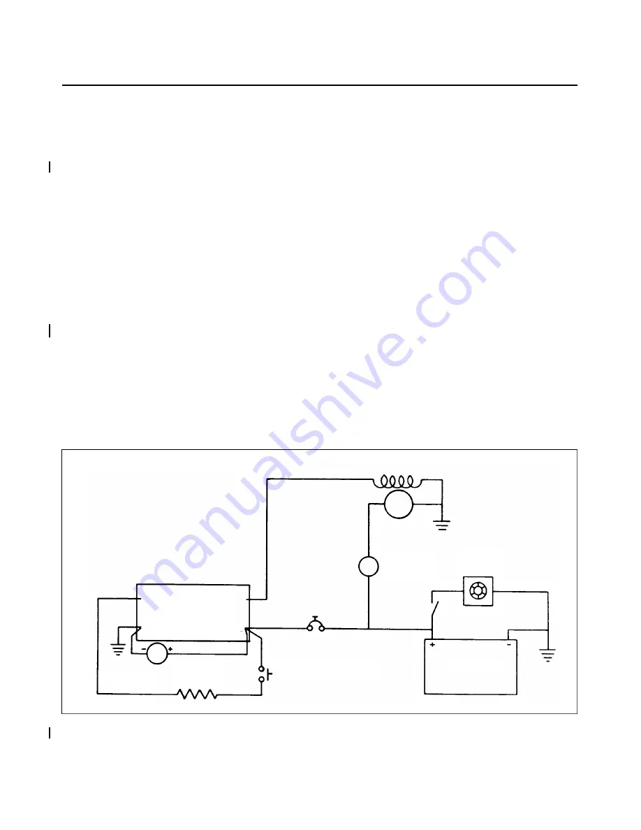
Connect the test meters and regulator wiring as shown in Figure 24-5.
2. All circuit connections must be clean and tight. This includes the test instrument connections which
MUST NOT come loose or open the charging circuit at any time while the system is operating.
3. The voltmeter will not indicate the true regulator setting until the regulator has been operating in the
c h a rging system or on the test bench for at least five minutes, at a charge rate of from 10 to 15
amperes.
Figure 24-5. Testing Lamar Model No. B-00288-1 Regulator
(S/N 44-7995001 thru 44-8195026 and all PA-44-180T’s)
PIPER AIRCRAFT
PA - 4 4 - 1 8 0 / 1 8 0 T
AIRPLANE MAINTENANCE MANUAL
24 -23-06
Page 24-18
Revised: June 20, 1995
1J6
1/2 W
2,200 OHM
PRECISION
V/M
BATTERY
CARBON
PILE
1
5 AMP
ALT
DC
AMMETER
PRESS — TO — TEST
NORMALLY OPEN
PAR FIELD
REGULATOR
UNDER TEST
GND BUS
2
1
V
Summary of Contents for SEMINOLE PA-44-180
Page 38: ...CHAPTER DIMENSIONS AND AREAS 1B14...
Page 49: ...CHAPTER LIFTING AND SHORING 1C1...
Page 53: ...CHAPTER LEVELING AND WEIGHING 1C5...
Page 58: ...CHAPTER TOWING AND TAXIING 1C10...
Page 62: ...CHAPTER PARKING AND MOORING 1C14...
Page 65: ...CHAPTER REQUIRED PLACARDS 1C17...
Page 70: ...CHAPTER SERVICING 1C22...
Page 98: ...CHAPTER STANDARD PRACTICES AIRFRAME 1E2...
Page 108: ...CHAPTER ENVIRONMENTAL SYSTEM 1E12...
Page 189: ...CHAPTER AUTOFLIGHT 1H21...
Page 192: ...CHAPTER COMMUNICATIONS 1H24...
Page 202: ...CHAPTER ELECTRICAL POWER 1I10...
Page 228: ...CHAPTER EQUIPMENT FURNISHINGS 1J12...
Page 233: ...CHAPTER FIRE PROTECTION 1J17...
Page 238: ...CHAPTER FLIGHT CONTROLS 1J24...
Page 304: ...2A18 CHAPTER FUEL...
Page 325: ...2B17 CHAPTER HYDRAULIC POWER...
Page 357: ...2D1 CHAPTER ICE AND RAIN PROTECTION...
Page 414: ...CHAPTER LANDING GEAR 2F13...
Page 479: ...2I6 CHAPTER LIGHTS...
Page 488: ...2I16 CHAPTER NAVIGATION AND PITOT STATIC...
Page 503: ...2J7 CHAPTER OXYGEN...
Page 524: ...2K6 CHAPTER VACUUM...
Page 535: ...2K19 CHAPTER ELECTRICAL ELECTRONIC PANELS AND MULTIPURPOSE PARTS...
Page 546: ...INTENTIONALLY LEFT BLANK PA 44 180 180T AIRPLANE MAINTENANCE MANUAL 2L6 PIPER AIRCRAFT...
Page 547: ...2L7 CHAPTER STRUCTURES...
Page 582: ...CHAPTER DOORS 3A18...
Page 593: ...CHAPTER STABILIZERS 3B8...
Page 604: ...CHAPTER WINDOWS 3B22...
Page 611: ...CHAPTER WINGS 3C10...
Page 624: ...CHAPTER PROPELLER 3D1...
Page 643: ...CHAPTER POWER PLANT 3D21...
Page 667: ...CHAPTER ENGINE FUEL SYSTEM 3F1...
Page 681: ...CHAPTER IGNITION 3F16...
Page 712: ...CHAPTER ENGINE INDICATING 3H1...
Page 730: ...CHAPTER EXHAUST 3H19...
Page 734: ...CHAPTER OIL 3I1...
Page 743: ...CHAPTER STARTING 3I11...
Page 755: ...CHAPTER TURBINES 3J1...


