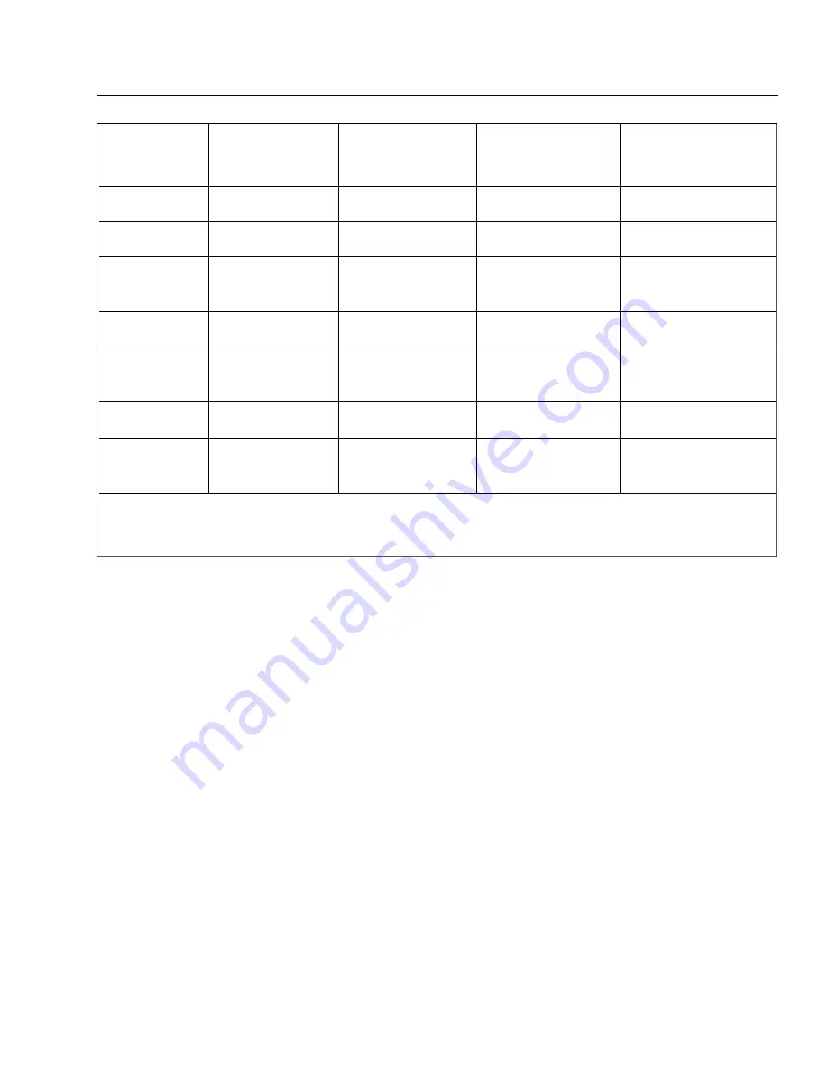
CHART 3202. TOE-IN, TOE-OUT CORRECTION
ALIGNMENT OF MAIN LANDING GEAR. (Refer to Figure 32-4.)
1. Place a straightedge no less than twelve feet long across the front of both main landing gear wheels. Butt
the straightedge against the tire at the hub level of the landing gear wheels. Jack the airplane up just high
enough to obtain a six and one-haU inch dimension between the centerline of the strut piston and the
centerline of the center pivot bolt of the gear torque links. Devise a support to hold the straightedge in this
position.
2. Set a square against the straightedge and check to see if its outstanding leg bears on the front and rear side
of the brake disc. (It may be necessary to remove the brake assembly to have clear access to the disc.) If it
touches both forward and rear flange, the landing gear is correctly aligned. The toe-in for the main landing
gear wheels is 0 ± 1/2 degrees.
— Note —
A carpenter's square, bccause of its especially long kgs, is recommended for checking
main landing gear wheel alignment.
3. If the square contacts the rear side of the d isc. Ieaving a gap between it and the front flange, the wheel is
toed-out. If a gap appears at the rear flange, the wheel is toed-in.
4. To rectify the toe-in and toe-out condition, remove the bolt connecting the upper and lower torque links and
TOE-IN
TOE-OUT
SHIM
WASHERS
WASHERS
AN 174
ANGLE
WASHERS
UNDER HEAD
UNDER NUT
BOLT
0°
AN960-416
AN960-416 (3)
-14
0° 33'
AN960-416
AN960-416
AN960-416 (2)
-14
0° 48'
AN960-416L
AN960-416
AN960-416
-14
AN960-416
1° 04'
AN960-416 (2)
AN960-416
AN960-416
-14
1° 19'
AN960-416L
AN960-416L
AN960-416
-14
AN960-416 (2)
1° 35'
AN960-416 (3)
AN960-416
AN960-416 (2)
-15
2° 05'
AN960-416 (4)
AN960-416
AN960-416
-15
Max. Allow.
AN960-416L Washers .031 Thick
AN960-416 Washers .062 Thick
PA - 4 4 - 1 8 0 / 1 8 0 T
AIRPLANE MAINTENANCE MANUAL
3 2 - 1 2 - 0 5
Page 32-19
Revised: May 15, 1989
2G11
PIPER AIRCRAFT
Summary of Contents for SEMINOLE PA-44-180
Page 38: ...CHAPTER DIMENSIONS AND AREAS 1B14...
Page 49: ...CHAPTER LIFTING AND SHORING 1C1...
Page 53: ...CHAPTER LEVELING AND WEIGHING 1C5...
Page 58: ...CHAPTER TOWING AND TAXIING 1C10...
Page 62: ...CHAPTER PARKING AND MOORING 1C14...
Page 65: ...CHAPTER REQUIRED PLACARDS 1C17...
Page 70: ...CHAPTER SERVICING 1C22...
Page 98: ...CHAPTER STANDARD PRACTICES AIRFRAME 1E2...
Page 108: ...CHAPTER ENVIRONMENTAL SYSTEM 1E12...
Page 189: ...CHAPTER AUTOFLIGHT 1H21...
Page 192: ...CHAPTER COMMUNICATIONS 1H24...
Page 202: ...CHAPTER ELECTRICAL POWER 1I10...
Page 228: ...CHAPTER EQUIPMENT FURNISHINGS 1J12...
Page 233: ...CHAPTER FIRE PROTECTION 1J17...
Page 238: ...CHAPTER FLIGHT CONTROLS 1J24...
Page 304: ...2A18 CHAPTER FUEL...
Page 325: ...2B17 CHAPTER HYDRAULIC POWER...
Page 357: ...2D1 CHAPTER ICE AND RAIN PROTECTION...
Page 414: ...CHAPTER LANDING GEAR 2F13...
Page 479: ...2I6 CHAPTER LIGHTS...
Page 488: ...2I16 CHAPTER NAVIGATION AND PITOT STATIC...
Page 503: ...2J7 CHAPTER OXYGEN...
Page 524: ...2K6 CHAPTER VACUUM...
Page 535: ...2K19 CHAPTER ELECTRICAL ELECTRONIC PANELS AND MULTIPURPOSE PARTS...
Page 546: ...INTENTIONALLY LEFT BLANK PA 44 180 180T AIRPLANE MAINTENANCE MANUAL 2L6 PIPER AIRCRAFT...
Page 547: ...2L7 CHAPTER STRUCTURES...
Page 582: ...CHAPTER DOORS 3A18...
Page 593: ...CHAPTER STABILIZERS 3B8...
Page 604: ...CHAPTER WINDOWS 3B22...
Page 611: ...CHAPTER WINGS 3C10...
Page 624: ...CHAPTER PROPELLER 3D1...
Page 643: ...CHAPTER POWER PLANT 3D21...
Page 667: ...CHAPTER ENGINE FUEL SYSTEM 3F1...
Page 681: ...CHAPTER IGNITION 3F16...
Page 712: ...CHAPTER ENGINE INDICATING 3H1...
Page 730: ...CHAPTER EXHAUST 3H19...
Page 734: ...CHAPTER OIL 3I1...
Page 743: ...CHAPTER STARTING 3I11...
Page 755: ...CHAPTER TURBINES 3J1...


