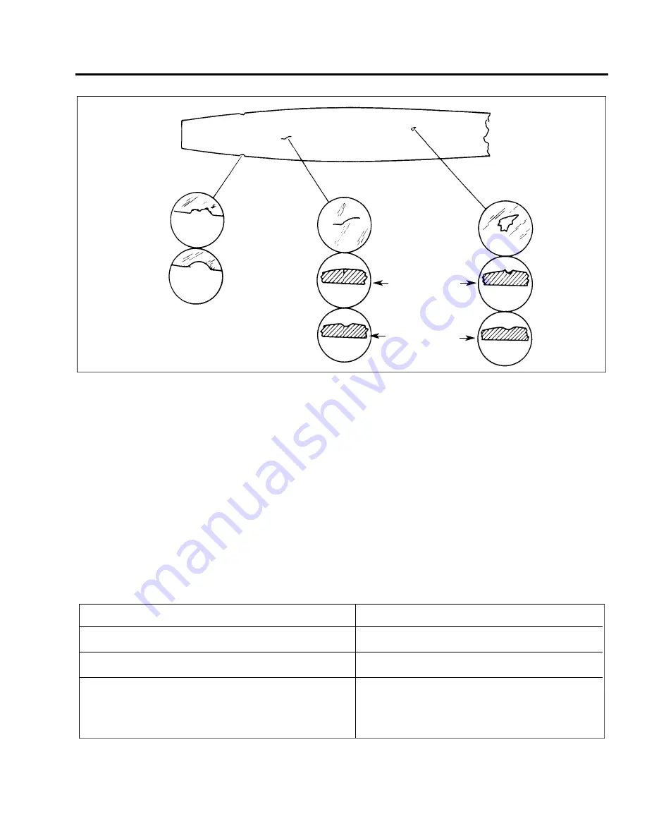
Figure 61-1. Typical Nicks and Removed Method
4. Observe the starter ring gear to make sure it is mounted properly on the engine crankshaft flange. One of
the bushings on the crankshaft is stamped with an “O” mark and it must be inserted in the starter ring gear
hole. Iikewise identified with an “O” mark.
5. Wipe crankshaft and propeller pilot to assure that no chips or foreign matter enter the propeller mechanism .
6. Check interior of propeller hub for proper seating of O-ring. Wipe inside of hub to remove any traces of dirt.
Check to see that O-ring is covered with grease.
7. Raise propeller into position so that each stud mates with an engine flange bushing and screw each stud in a
few threads at a time until all are tight. Torque to 60 to 70 foot pounds. (Refer to Figure 61-2 for additional
information on three blade propeller installation.)
8. Check the propeller blade track.
9. Safety the propeller mounting bolts with MS20995-C41 safety wire.
10. Install the spinner torque cap bolts 35 to 40 inch pounds.
CHART 6101. PROPELLER TORQUE LIMITS
EXAGGERATED VIEW OF
NICK IN LEADING EDGE
BEFORE
AFTER
BLEND DEEPEST
PORTION OF NICKS
INTO LEADING EDGE
ALIGNMENT WITH
SMOOTH CURVES
NOTE: RECOMMENDED METHOD FOR REMOVING
NICKS, CRACKS, AND SCRATCHES IS BY
USING RIFFLE FILE AND/OR CROCUS CLOTH.
EXAGGERATED VIEW OF
SURFACE CRACK
CROSS-SECTION
BEFORE REPAIR
CROSS-SECTION
AFTER REPAIR
EXAGGERATED VIEW OF
NICK IN FACE OF BLADE
DESCRIPTION
REQUIRED TORQUE
Propeller Mounting Nuts
60 - 70 Foot-Pounds
Forward Bulkhead Attachment Bolts
20 - 22 Foot-Pounds
Spinner Attachment Screws
20 - 25 Inch-Pounds
PA - 4 4 - 1 8 0 / 1 8 0 T
AIRPLANE MAINTENANCE MANUAL
6 1 - 11 - 0 3
Page 61-02
Revised: May 15, 1989
3D4
PIPER AIRCRAFT
Summary of Contents for SEMINOLE PA-44-180
Page 38: ...CHAPTER DIMENSIONS AND AREAS 1B14...
Page 49: ...CHAPTER LIFTING AND SHORING 1C1...
Page 53: ...CHAPTER LEVELING AND WEIGHING 1C5...
Page 58: ...CHAPTER TOWING AND TAXIING 1C10...
Page 62: ...CHAPTER PARKING AND MOORING 1C14...
Page 65: ...CHAPTER REQUIRED PLACARDS 1C17...
Page 70: ...CHAPTER SERVICING 1C22...
Page 98: ...CHAPTER STANDARD PRACTICES AIRFRAME 1E2...
Page 108: ...CHAPTER ENVIRONMENTAL SYSTEM 1E12...
Page 189: ...CHAPTER AUTOFLIGHT 1H21...
Page 192: ...CHAPTER COMMUNICATIONS 1H24...
Page 202: ...CHAPTER ELECTRICAL POWER 1I10...
Page 228: ...CHAPTER EQUIPMENT FURNISHINGS 1J12...
Page 233: ...CHAPTER FIRE PROTECTION 1J17...
Page 238: ...CHAPTER FLIGHT CONTROLS 1J24...
Page 304: ...2A18 CHAPTER FUEL...
Page 325: ...2B17 CHAPTER HYDRAULIC POWER...
Page 357: ...2D1 CHAPTER ICE AND RAIN PROTECTION...
Page 414: ...CHAPTER LANDING GEAR 2F13...
Page 479: ...2I6 CHAPTER LIGHTS...
Page 488: ...2I16 CHAPTER NAVIGATION AND PITOT STATIC...
Page 503: ...2J7 CHAPTER OXYGEN...
Page 524: ...2K6 CHAPTER VACUUM...
Page 535: ...2K19 CHAPTER ELECTRICAL ELECTRONIC PANELS AND MULTIPURPOSE PARTS...
Page 546: ...INTENTIONALLY LEFT BLANK PA 44 180 180T AIRPLANE MAINTENANCE MANUAL 2L6 PIPER AIRCRAFT...
Page 547: ...2L7 CHAPTER STRUCTURES...
Page 582: ...CHAPTER DOORS 3A18...
Page 593: ...CHAPTER STABILIZERS 3B8...
Page 604: ...CHAPTER WINDOWS 3B22...
Page 611: ...CHAPTER WINGS 3C10...
Page 624: ...CHAPTER PROPELLER 3D1...
Page 643: ...CHAPTER POWER PLANT 3D21...
Page 667: ...CHAPTER ENGINE FUEL SYSTEM 3F1...
Page 681: ...CHAPTER IGNITION 3F16...
Page 712: ...CHAPTER ENGINE INDICATING 3H1...
Page 730: ...CHAPTER EXHAUST 3H19...
Page 734: ...CHAPTER OIL 3I1...
Page 743: ...CHAPTER STARTING 3I11...
Page 755: ...CHAPTER TURBINES 3J1...


