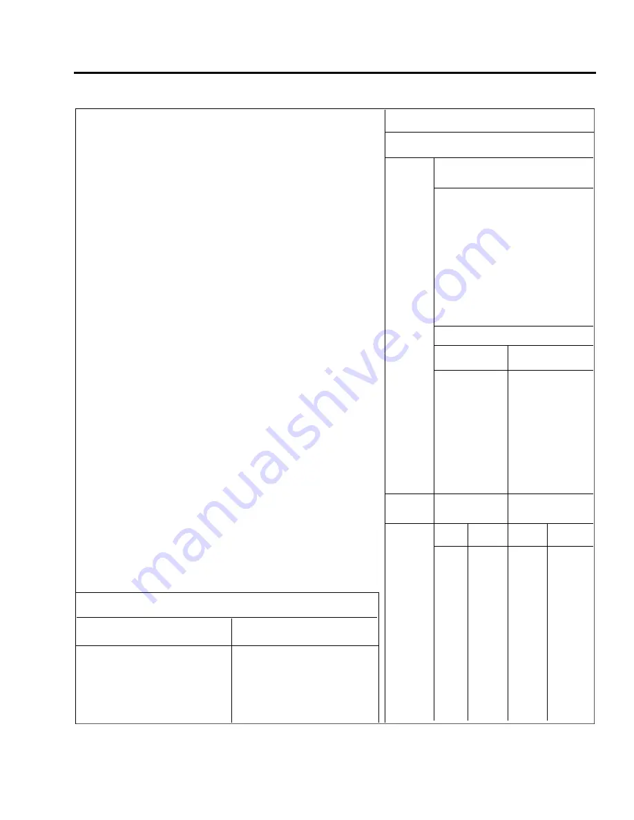
CHART 9102. RECOMMENDED NUT TORQUES
TO R Q U E S : The importance of correct application can not be overemphasized.
Undertorque can result in unnecessary wear of nuts and bolts as well as the parts
they are holding together. When insufficient pressures are applied, uneven loads
will be transmitted throughout the assembly which may result in excessive wear or
premature failure due to fatigue. Overtorque can be equally damaging because of
failure of a bolt or nut from overstressing the threaded areas. The following
procedures should be followed to assure that the correct torque is applied:
1.
Self-Locking Fasteners - Add the friction torque from Chart “A” for sizes 8
through 7/16 to the recommended torque from Chart “B” to get the final
torque. This would be the actual reading on the torque wrench. To determine
friction drag torque for sizes 1/2 through 1 1/4, turn the nut fully on to the bolt
and determine the torque required to turn the nut. Add this friction drag torque
to the torque given in Chart “B”.
2.
Castellated and Non-Self Locking Nuts - Use only the torque given in Chart
“B”. Unless otherwise specified, when castellated nuts are used with a cotter
pin on moving joints, do not torque the nut. Turn the nut onto the bolt until
proper grip is established and alignment with the cotter pin hole is achieved.
Then install the cotter pin.
GENERAL REQUIREMENTS.
1.
Calibrate the torque wrench periodically to assure accuracy. Recheck
frequently.
2.
Ascertain that the bolt and nut threads are clean and dry (unless otherwise
specified by the manufacturers.) If the bolt or nut is required to be lubricated
prior to tightening, the torque range should be reduced 50 percent.
3.
Use a bolt long enough to prevent bearing loads on the threads. The
complete chamfer or end radius of the bolt or screw must extend through the
nut.
4.
Unique torques specified in the text of this manual supercede the torques
given in Charts “A” and “B”.
5.
Refer o the latest revision of Lycoming Service Table Limits, SSP1776, for
torques on parts used on Lycoming engines.
6.
A maximum of two AN960 washers may be added under bolt heads or nuts to
correct for variations in material thickness within the tolerances permitted.
7.
Self-Locking Fasteners - Limitations of the use of self-locking nuts, bolts and
screws including fasteners with non-metallic inserts are as follows:
A.
Fasteners incorporating self-locking devices shall not be reused if they
can be run-up using only fingers. They may be reused if hand tools are
required to required to run them up providing there is no obvious damage
to the self-locking device prior to installation.
B.
Bolts 5/16 inch diameter and over with cotter pin holes may be used with
self-locking nuts. Nuts with non-metallic locking devices may be used in
this application only if the bolts are free from burrs around the cotter pin
hole.
C.
Do not use self-locking nuts at joints which subject either the nut or bolt
to rotate.
D.
Never tap or rethread self-locking fasteners. Do not use nuts, bolts or
screws with damaged threads or rough ends.
CHART A
BOLT
FRICTION DRAG
SIZE
TORQUE (IN. -LB.)
8 (course thread)
15
10
18
1/4
30
5/16
60
3/8
80
7/16
100
CHART B
COARSE THREAD SERIES
BOLTS
Steel Tension
AN 3 THROUGH AN 20
AN 42 THROUGH AN 49
AN 73 THROUGH AN 81
AN 173 THROUGH AN 186
MS 20033 THROUGH MS 20046
MS 20073
MS 20074
AN 509 NK9
MS 24694
AN 525 NK525
MS 27039
NUTS
Steel Tension
Steel Shear
AN 310
AN 320
AN 315
AN 364
AN 363
NAS 1022
AN 365
MS 17826
NAS 1021
MS 20364
MS 17825
MS 21045
MS 20365
MS 20500
NAS 679
Nut-bolt
Torque Limits
Torque Limits
size
in-lbs.
in-lbs.
Min.
Max.
Min.
Max.
8-32
12
15
7
9
10-24
20
25
12
15
1/4-20
40
50
25
30
5/16-18
80
90
48
55
3/8-16
160
185
95
110
7/16-14
235
255
140
155
1/2-13
400
480
240
290
9/16-12
500
700
300
420
5/8-11
700
900
420
540
3/4-10
1,150
1,600
700
950
7/8-9
2,200
3,000
1,300
1,800
1-8
3,700
5,000
2,200
3,000
1-1/8-8
5,500
6,500
3,300
4,000
1-1/4-8
6,500
8,000
4,000
5,000
PA - 4 4 - 1 8 0 / 1 8 0 T
AIRPLANE MAINTENANCE MANUAL
9 1 - 0 1 - 0 1
Page 91-02
Revised: May 15, 1989
4A21
PIPER AIRCRAFT
Summary of Contents for SEMINOLE PA-44-180
Page 38: ...CHAPTER DIMENSIONS AND AREAS 1B14...
Page 49: ...CHAPTER LIFTING AND SHORING 1C1...
Page 53: ...CHAPTER LEVELING AND WEIGHING 1C5...
Page 58: ...CHAPTER TOWING AND TAXIING 1C10...
Page 62: ...CHAPTER PARKING AND MOORING 1C14...
Page 65: ...CHAPTER REQUIRED PLACARDS 1C17...
Page 70: ...CHAPTER SERVICING 1C22...
Page 98: ...CHAPTER STANDARD PRACTICES AIRFRAME 1E2...
Page 108: ...CHAPTER ENVIRONMENTAL SYSTEM 1E12...
Page 189: ...CHAPTER AUTOFLIGHT 1H21...
Page 192: ...CHAPTER COMMUNICATIONS 1H24...
Page 202: ...CHAPTER ELECTRICAL POWER 1I10...
Page 228: ...CHAPTER EQUIPMENT FURNISHINGS 1J12...
Page 233: ...CHAPTER FIRE PROTECTION 1J17...
Page 238: ...CHAPTER FLIGHT CONTROLS 1J24...
Page 304: ...2A18 CHAPTER FUEL...
Page 325: ...2B17 CHAPTER HYDRAULIC POWER...
Page 357: ...2D1 CHAPTER ICE AND RAIN PROTECTION...
Page 414: ...CHAPTER LANDING GEAR 2F13...
Page 479: ...2I6 CHAPTER LIGHTS...
Page 488: ...2I16 CHAPTER NAVIGATION AND PITOT STATIC...
Page 503: ...2J7 CHAPTER OXYGEN...
Page 524: ...2K6 CHAPTER VACUUM...
Page 535: ...2K19 CHAPTER ELECTRICAL ELECTRONIC PANELS AND MULTIPURPOSE PARTS...
Page 546: ...INTENTIONALLY LEFT BLANK PA 44 180 180T AIRPLANE MAINTENANCE MANUAL 2L6 PIPER AIRCRAFT...
Page 547: ...2L7 CHAPTER STRUCTURES...
Page 582: ...CHAPTER DOORS 3A18...
Page 593: ...CHAPTER STABILIZERS 3B8...
Page 604: ...CHAPTER WINDOWS 3B22...
Page 611: ...CHAPTER WINGS 3C10...
Page 624: ...CHAPTER PROPELLER 3D1...
Page 643: ...CHAPTER POWER PLANT 3D21...
Page 667: ...CHAPTER ENGINE FUEL SYSTEM 3F1...
Page 681: ...CHAPTER IGNITION 3F16...
Page 712: ...CHAPTER ENGINE INDICATING 3H1...
Page 730: ...CHAPTER EXHAUST 3H19...
Page 734: ...CHAPTER OIL 3I1...
Page 743: ...CHAPTER STARTING 3I11...
Page 755: ...CHAPTER TURBINES 3J1...


