background image

23

TAURUS ELECTRO

www.pipistrel.si

REV. 0

Motor failure in climb

First ensure proper airspeed by lowering the nose, then start scanning the terrain underneath and 

choose the most appropriate site for landing out.

WARNING!


THE DECISION WHERE TO LAND WHEN LANDING OUT IS FINAL! CHANGING 

YOUR MIND EVEN IF YOU HAPPEN TO COME ACROSS A DIFFERENT, PERHAPS MORE APPROPRI

ATE LANDING SITE, SHOULD BE YOUR LAST RESORT.

Provided the motor fails aloft, first retract the propulsion unit and prepare for an 

emergency landing if the conditions prevent you from gliding to the airport.

Emergency landing

Propulsion unit retracted 

1. Master switch OFF (key in full left position).

2. Fasten your seat belts tightly.

3. Approach and land with extreme caution with +10 km/h (+5 kts) airspeed reserve if  

     the chosen landing terrain lenght permits.

4. After having landed abandon the aircraft immediately.

Propulsion unit extended or refusing to retract

1. Your first priority is to fly the aircraft! Atempt to retract the propulsion unit by 

setting the retraction switch up and back down IF your height is 300 m or higher. 

Otherwise, proceed with emergency landing. 

2. Fasten your seat belts tightly.

3. Master switch OFF (key in full left position).

4. Should the propulsion unit remain extended or partially retracted land the aircraft     

onto the main wheels first in order to minimise vertical impact onto the propeller arm. 

5. Fly no faster than minimum sink speed (94 km/h - 51 kts) during the approach as 

more speed will only increase your rate of descent and use  up to+10 km/h (+5 kts) air-

speed reserve only before touchdown if  the chosen landing terrain lenght permits.

The landing out manoeuvre MUST be preformed with regard to all normal flight parameters.

Emergency procedures

Summary of Contents for Taurus ELECTRO G2

Page 1: ...ockpit at all times Should you be selling the aircraft make sure this manual is handed over to the new owner REV 0 9 March 2011 This is the original manual of Pipistrel d o o Ajdov ina Should third pa...

Page 2: ...ont ballast Available crew weight 9 kg front ballast Available luggage weight List of equipment included in aircraft empty weight Date and place of issue Ajdov ina To log into the Owner s section rece...

Page 3: ...iginal date of Approval March 2011 This aircraft is to be operated in compliance with information and limitations contained herein The original English Language edition of this manual has been approve...

Page 4: ...All revised pages should be clearly designated in the upper right corner of the page also any changes in page content should be clearly visible e g marked with a bold black vertical line Name of revis...

Page 5: ...visions 4 REV 0 List of valid pages 5 REV 0 Table of contents 7 REV 0 General 9 12 REV 0 Limitations 13 20 REV 0 Emergency procedures 21 28 REV 0 Normal procedures 29 42 REV 0 Performance 43 51 REV 0...

Page 6: ...6 TAURUS ELECTRO www pipistrel si REV 0 This page is intentionally left blank...

Page 7: ...US ELECTRO www pipistrel si REV 0 Table of contents General Limitations Emergency procedures Normal procedures Performance Weight and balance Aircraft and systems on board Handling and maintenance App...

Page 8: ...8 TAURUS ELECTRO www pipistrel si REV 0 This page is intentionally left blank...

Page 9: ...9 TAURUS ELECTRO www pipistrel si REV 0 Introduction Notes and remarks Technical data 3 view drawing General General...

Page 10: ...r electronic web or printed without the prior consent of PIPISTREL d o o Ajdovscina Notes and remarks Safety definitions used in the manual WARNING DISREGARDING THE FOLLOWING INSTRUCTIONS WILL LEAD TO...

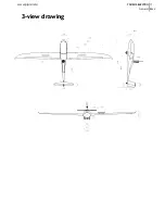
Page 11: ...11 TAURUS ELECTRO www pipistrel si REV 0 3 view drawing General...

Page 12: ...12 TAURUS ELECTRO www pipistrel si REV 0 This page is intentionally left blank...

Page 13: ...0 Introduction Operational velocities Motor fuel oil Weight limits Centre of gravity limits Manoeuvre limits G load factors Cockpit crew Types of operations Minimum equipment list Other restrictions W...

Page 14: ...ers above this speed Once fully extended VNE is the limit VLO Max ldg down speed 163 88 Do not fly with landing gear extended above this speed Airspeed indicator markings MARKING IAS km h kts Definiti...

Page 15: ...at sea level Altitude meters Altitude meters 0 500 1000 1500 2000 2500 3000 3500 4000 4500 5000 Altitude flight level 0 FL16 FL33 FL50 FL66 FL82 FL98 FL115 FL131 FL148 FL165 VNE IAS km h 220 215 211 2...

Page 16: ...recommended max continous temperature 45 55 C WARNING DO NOT UNDER ANY CIRCUMSTANCES ATTEMPT TO USE ANY OTHER BATTERIES OTHER THAN PIPISTREL FACTORY ORIGINAL BATTERY SYSTEM WITH THIS MOTOR CONTROLLER...

Page 17: ...inimum combined cockpit crew weight depends on C G of empty aircraft see p 55 maximum combined cockpit crew weight depends on C G of empty aircraft see p 55 water ballance reservoir max weight 9 kg al...

Page 18: ...at VA at VNE max positive wing load 5 3 G 4 0 G max negative wing load 2 65 G 1 5 G Cockpit crew Actual minumum and maximum combined cockpit crew weight heavily depend on the centre of gravity of an e...

Page 19: ...eter functional Compass functional Electric System Manager instrument ESYS MAN Battery Management System BMS functional Parachute rescue system where required legally Other restrictions Due to flight...

Page 20: ...ttle idle ignition off 2 reduce IAS to 75 km h 3 after prop stops IAS 90 km h engine DOWN 4 when prop retracted master switch I VARIO RADIO AUX XPDR 12V socket ENG INST ENG SYSTEM T INTERCOM ON OFF L...

Page 21: ...ilure Landing out Motor fire Smoke in cockpit ESYS MAN failure Landing gear failure Flutter Exceeding VNE Parachute rescue system Emergencyprocedures Emergencyprocedures Emergencyprocedures Emergencyp...

Page 22: ...ly after having spun for a mere 90 WARNING KEEP THE CONTROL STICK CENTRED ALONG ITS LATERAL AXIS NO AILERON DEFLECTIONS THROUGHOUT THE RECOVERY PHASE DO NOT ATTEMPT TO STOP THE AIR CRAFT FROM SPINNING...

Page 23: ...e if the chosen landing terrain lenght permits 4 After having landed abandon the aircraft immediately Propulsion unit extended or refusing to retract 1 Your first priority is to fly the aircraft Atemp...

Page 24: ...Open slide windows and set all ventilation devices to ON 3 Perform side slip crab manoeuvre in direction opposite the fire 4 Perform emergency landing procedure and abandon the aircraft immediately B...

Page 25: ...even the whole aircraft start to vibrate violently Should flutter occur pull on the stick and reduce power immediately WARNING FLUTTERING OF AILERONS OR TAIL SURFACES MAY CAUSE PERMANENT STRUCTURAL D...

Page 26: ...AS SOON AS THE PILOT BOARDS THE AIRCRAFT SAFETY PIN MUST BE REMOVED Use of parachute rescue system In situations such as structural failure mid air collision loss of control over aircraft motor failu...

Page 27: ...itate and immediately contact the manufacturer Handling and maintenance of Parachute rescue system Prior to every flight all visible parts of the system must be checked for proper condition Special at...

Page 28: ...28 TAURUS ELECTRO www pipistrel si REV 0 Emergency procedures This page is intentionally left blank...

Page 29: ...Assembling and disassembling the aircraft Daily check up Preflight check up Normal procedures and recommended speeds Normalprocedures Normalprocedures Normalprocedures Normalprocedures Normalprocedure...

Page 30: ...t make sure the spoiler and flap connectors have fitted into adequate fuselage fittings prop erly At the same time the person holding the wingtip must start with slight circular move ments 1cm each di...

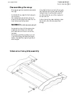
Page 31: ...he person in the cock pit remove the main spar pins one by one smoothly Forcing pins out of their position may result in structural damage therefore the wingtip holders must hold the wing halfs precis...

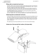
Page 32: ...UST be united during the following procedure To fit the horizon tal tail surfaces first set the trim handle inside the cockpit to full forward position Make sure the pins their holes and bushings have...

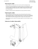
Page 33: ...ts tightened check full rudder deflections for smooth unobstructed movement Detaching the rudder Deflect the rudder to one side fully and unscrew the nut of the bolt with which the rudder is at tached...

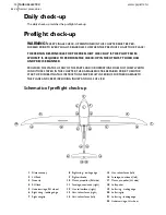
Page 34: ...ER THE DAMAGE MUST BE REPAIRED PRIOR TO MOTOR START UP DISOBEYING THIS INSTRUCTIONS MAY RESULT IN SERIOUS FURTHER DAMAGE TO THE PLANE AND CREW INCLUDING INJURY AND LOSS OF LIFE Schematic of preflight...

Page 35: ...racks no wavy patterns impact spots Fuselage cannopy frame joint equal spacing perfect closure Undercarriage wheels Bolts fastened Wheel no mechanical damage e g cracks clean Wheel axis and nut fasten...

Page 36: ...arations along main chord Surface condition pristine no cracks impact spots or bumps no paint and or edge separations Horizontal tail surfaces Surface condition pristine no cracks impact spots or bump...

Page 37: ...and in position Seat belts undamaged verify unobstructed harness opening fastening points intact Glass cannopy perfect closing at all points smooth opening hinges firmly attached glass immacu lately c...

Page 38: ...ISE YOU MAY BUMP INTO THE CANOPY OVERHEAD Motor start up Before motor start up CAUTION TO ENSURE PROPER AND SAFE USE OF AIRCRAFT IT IS ESSENTIAL FOR ONE TO FAMILIARISE WITH MOTOR S LIMITATIONS AND MOT...

Page 39: ...COOL DOWN THE MOTOR FASTER Take off and initial climb Before lining up verify the following Spoilers retracted and secured Battery charge status and health sufficient and OK Safety belts fastened Cabi...

Page 40: ...peed and continue flying with flaps set to neutral position CAUTION IN ROUGH AIR EXTEND AIRBRAKES UNPOWERED FLIGHT FOR SHORT TIME IF NECESSARY TO KEEP AIRSPEED BELOW VRA Descent and final approach Lan...

Page 41: ...UND SHOULD THIS OCCUR HOLD THE ELEVATOR STEADY UNDER NO CIRCUMSTANCES ATTEMPT TO FOLLOW AIRCRAFT S MOVEMENT WITH ELEVATOR DEFLECTIONS SINCE TAURUS ELECTRO TENDS TO ATTENUATE REBOUNDING BY ITSELF HOWEV...

Page 42: ...e knob left and select engine DOWN Reduce speed to 80 km h 43 kts and set flaps to 1st stage Continue decellerating towards 70 km h 40 kts The system will complete the retraction extension by itself O...

Page 43: ...pipistrel si REV 0 Introduction Airspeed indicator calibration Take off performance Climb performance Cruise Descent Landing performance Maneuver gust envelope Speed polar Additional technical data Pe...

Page 44: ...up 75 km h 40 5 kts flaps in neutral position 0 neutral 71 km h 38 3 kts flaps in 1st position 5 down 68 km h 36 7 kts flaps in T position 9 down 65 km h 35 0 kts flaps in L position 18 down 63 km h...

Page 45: ...ltitude increases Effect of the wind Wind head cross or downwind also called tailwind affects aircraft s ground speed GS Headwind on takeoff and landing causes the Takeoff and Landing runway length to...

Page 46: ...es data about the effect of headwind and tailwind on takeoff runway length windspeed m s 3 2 1 0 2 4 6 windspeed kts 6 4 2 0 4 8 12 Takeoff runway length m ft Electro 297 975 243 800 205 670 160 520 1...

Page 47: ...data about the effect of elevation on climb rate at best climb speed Vy Taurus Electro 0 m 0 ft 3 1 m s 620 fpm 500 m 1600 ft 2 9 m s 580 fpm 1000 m 3300 ft 2 7 m s 540 fpm 1500 m 5000 ft 2 5 m s 500...

Page 48: ...AND SHOULD ONLY BE ATTEMTED BY EXPERIENCED PILOTS AND AT OWN RISK Crosswind landing limitations Maximum allowed crosswind speed for landing with flaps in L position as well as take off with flaps in T...

Page 49: ...0 4 00 1 50 2 65 2 04 4 81 2 81 4 04 4 3 2 1 0 1 2 3 4 5 6 0 20 40 60 80 100 120 140 160 180 200 220 240 260 280 300 EAS km h load factor manouever and gust TAURUS 360kg flap 0 6 96 5 25 1 97 3 48 2 6...

Page 50: ...50 TAURUS ELECTRO www pipistrel si REV 0 Speed polar 472 kg prop unit landing gear retracted optimal flap settings Performance...

Page 51: ...max sink rate with spoilers extended 5 8 m s 1160 fpm best glide ratio speed 108 km h 58 kts takeoff runway length at MTOM 160 m 525 ft takeoff runway length at MTOM over 15 m obst 245 m 800 ft best g...

Page 52: ...52 TAURUS ELECTRO www pipistrel si REV 0 This page is intentionally left blank...

Page 53: ...alance Weightandbalance Weightandbalance Weightandbalance Weightandbalance Weightandbalance Weightandbalance Introduction Weighing and centre of gravity calculation for empty mass Weight and Balance r...

Page 54: ...ale readings subtract eventual tare weight in order to get net weight NOTE IF ACCURATE HIGH RANGE SCALES FOR MAIN WHEELS ARE NOT AVAILABLE AIR CRAFT EMPTY MASS MAY BEDETERMINED BY ADDING UP MASSES OF...

Page 55: ...ion Fill up Weight and Balance report on the next page Empty mass c g limits diagram is used to find out maximum and minimum cockpit load with respect to mass and centre of gravity of empty aircraft E...

Page 56: ...G2 b Gempty a Useful load distribution 13 5 2 7 4 5 2 7 4 5 2 7 4 5 2 7 4 5 2 7 4 5 2 7 4 5 2 7 4 g k s s a m x a m 14 max useful load 13 10 kg 175 5 175 5 179 5 15 max cockpit load without w ballast...

Page 57: ...0 kg at the bottom horizontal axis and draw a vertical line through it 3 The intersection of two lines drawn determines minimum cockpit load Interpolate between lines of constant minimum cockpit load...

Page 58: ...distribution of useful load items are explained below However the influence of useful load items is briefly expressed in the condition that if for a given empty mass and c g the max useful max and min...

Page 59: ...ments of all items add up masses of all items divide the sum of moments kg mm by the sum of masses kg to obtain flight mass c g mm Reference masses and c g s of different items masses and c g s of dif...

Page 60: ...60 TAURUS ELECTRO www pipistrel si REV 0 This page is intentionally left blank...

Page 61: ...s and safety belts Pitot static lining Air brakes spoilers Flap settings Power plant propeller Energy storage charging Electrical system Cooling system Wheel brake system Aircraftandsystemsonboard Air...

Page 62: ...ls can be adjusted to suit your size and needs The batteries are in the fuselage placed in four metal boxes with dedicated connectors Charging must be carried out only with origi nal Pipistrel dedicat...

Page 63: ...arts are made of glass carbon and kevlar fiber manufactured by Interglas GmbH All composite parts have been tested at a safety factor of 1 875 All parts are made in moulds therefore no shape or struct...

Page 64: ...vidual control levers pilot stick rudeer pedals with belonging length adjustment levers Shared control levers ESYS MAN throttle control flap lever gear retraction lever trim lever air brakes lever can...

Page 65: ...ractable wheels and a rudder guided tail wheel Main gear is retcracted lowered by operating a lever located between both seats accessible to both crew Once main gear is lowered it is locked into posit...

Page 66: ...and 18 flaps there are recommendations for the use of flaps with different speed ranges and types of flight operation Recommended speed ranges for certain flap settings in when gliding flaps in negati...

Page 67: ...extended or retracted This process is fully automated the propeller is posi tioned and held in place while the motor extends or retracts The pilot only selects the desired mode with the toggle switch...

Page 68: ...last to be disabled during the operation of the propulsion system System Status LED Green means ON OK permanent RED is ERROR see screen for error message Only active when System enable is set to ON P...

Page 69: ...e bar indicator Retracting the propeller arm WARNING BEFORE RETRACTING THE PROPELLER ARM IN FLIGHT SET FLAPS TO T STAGE AND REDUCE SPEED TO 80 KM H 45 KTS A COOLING PERIOD IS NOT REQUIRED 1 Reduce RPM...

Page 70: ...or storage it is recommended to disconnect the RED power connector on the box behind the cockpit section This will physically disconnect the high voltage part of the propulsion system Make sure you re...

Page 71: ...ge time will vary upon battery charge status and may be between 30 minutes to up to 7 hours The charger is a world wide chager which can be connected to any 110 V and 240 V 50 Hz or 60 Hz electrical g...

Page 72: ...72 TAURUS ELECTRO www pipistrel si REV 0 Aircraft and systems on board Schematic of complete electrical system...

Page 73: ...eel brake system features common braking action for both main wheels Wheel brakes are hy draulicly driven disc type Wheel brakes are operated by extending the airbrake lever past the full extension po...

Page 74: ...74 TAURUS ELECTRO www pipistrel si REV 0 Aircraft and systems on board This page is intentionally left blank...

Page 75: ...oduction Inspection periods Repairs and spare part replacements Preventative maintenance Special check ups Draining and refuelling Tie down Storage Cleaning Keeping your aircraft in perfect shape Hand...

Page 76: ...Check up visual only check for free play and whether everything is in position DO IT YOURSELF CL Cleaning DO IT YOURSELF LO Lubricating oiling lubricate all designated parts and spots using proper lu...

Page 77: ...tors SC UNDERCARRIAGE O tires C C R wheel axis and wheels C wheel bearings C SC R wheel fairings C C C tail wheel mounting bolt check and fasten every 50 landings CONTROLS R general free play C C SC c...

Page 78: ...d clean cooling duct heatsink before each flight ENERGY STORAGE SYSTEM ENERGY STORAGE SYSTEM Perform the keep alive refreshment charge once every 30 days as per page 71 Perform fill up charge 24 hours...

Page 79: ...TION PERFORM THIS OPERATION ONLY ONCE AFTER FIRST 50 FLIGHT HOURS CHECK SPOILERS THOROUGHLY FOR UNOBSTRUCTED SMOOTH AND EVEN EXTENTION BEFORE EVERY FLIGHT Schematic of spoilers airbrakes drive fine ad...

Page 80: ...r or in cold temperatures you may encounter click clack like noises above your head The remedy for this unpleasant noise is to add washers tipically of 0 5 mm thickness in between wing and fuselage Wa...

Page 81: ...ary the air bubbles in the hydraulic lining which is causing the problem The main wheel s main axis nut especially after a wheel and or axis replacementnut may be tight ened incorrectly so that the br...

Page 82: ...intain their original stiffness As for the parachute rescue system make sure the activation handle safety pin is inserted every time you leave the aircraft CAUTION SHOULD THE AIRCRAFT BE STORED AND OR...

Page 83: ...and a drying towel chamois artificial leather skin This will be very easy to do if you applied a coat of Pronto before flight Detailed handling Airframe cleaning instructions Every day care after flig...

Page 84: ...long the whole span of the gasket Ultimately you may wish to apply Teflon grease in spray over the area where the gaskets touch the control surfaces Polishing by hand Use only the highest quality poli...

Page 85: ...85 TAURUS ELECTRO www pipistrel si REV 0 Conversion tables Preflight check up pictures Appendix Appendix Appendix Appendix Appendix Appendix Appendix Appendix...

Page 86: ...4 14 7 55 87 10 47 25 36 148 25 80 43 16 27 79 15 8 09 88 95 48 25 90 150 10 51 43 70 29 65 16 8 63 90 80 49 26 44 151 96 82 44 24 31 50 17 9 17 92 66 50 26 98 153 81 83 44 78 33 35 18 9 71 94 51 51 2...

Page 87: ...100 ft min m sec 100 ft min m sec 100 ft min m sec 100 ft min 0 50 1 1 96 10 66 21 41 33 20 82 41 80 70 1 01 2 3 93 11 17 22 43 30 21 33 42 82 67 1 52 3 5 90 11 68 23 45 27 21 84 43 84 64 2 03 4 7 87...

Page 88: ...42 1 029 3 000 914 9 056 48 30 0 896 0 915 1 045 4 000 1219 7 075 44 73 0 863 0 888 1 061 5 000 1524 5 094 41 16 0 832 0 861 1 077 6 000 1829 3 113 37 60 0 801 0 835 1 090 1 000 2134 1 132 34 03 0 771...

Page 89: ...18 4 267 14 45 93 14 32 47 154 1 24 38 80 262 46 4 572 15 49 21 14 63 48 157 4 24 68 81 265 74 4 876 16 52 49 14 93 49 160 7 24 99 82 269 02 5 181 17 55 77 15 24 50 164 1 25 29 83 272 31 5 48 18 59 0...

Page 90: ...5 250 1043 7 30 8 2050 790 0 23 3 200 1037 5 30 6 2100 785 1 23 2 150 1031 4 30 5 2150 780 2 23 0 100 1025 3 30 3 2200 775 3 22 9 50 1019 3 30 1 2250 770 5 22 8 0 1013 3 29 9 2300 165 7 22 6 50 1007...

Page 91: ...4 337 8 15 3 800 2625 9 8 282 8 0 981 690 6 9389 0 908 0 115 1 134 0 925 1 039 337 4 15 4 900 2953 9 1 282 1 0 979 682 3 9276 0 897 0 114 1 123 0 916 1 044 337 15 5 1000 3281 8 5 281 5 0 977 674 1 916...

Page 92: ...ing edge Nose Pitot tube Ventilation 3 5 Wing root Cockpit Cockpit Cockpit aft Cockpit aft Wing root Wing root Undercarriage RH wheel Undercarriage RH wheel Starboard wing leading edge Starboard wing...

Page 93: ...10 Wing root Horizontal tail surfaces 12 13 Vertical tail surfaces Propulsion system 10 11 Motor bay door Starboard wingtip Starboard wingtip Starboard wing trailing edge Starboard wing trailing edge...

Page 94: ...94 TAURUS ELECTRO www pipistrel si REV 0 This page is intentionally left blank...

Page 95: ...additional and or spare parts are replaced with non original parts in case additional equipment is built in without Pipistrel d o o s prior knowledge in case the purchased goods were changed or modifi...

Page 96: ...strel d o o Ajdov ina podjetje za alternativno letalstvo Gori ka cesta 50a SI 5270 Ajdov ina Slovenija tel 386 0 5 3663 873 fax 386 0 5 3661 263 e mail info pipistrel si www pipistrel si www pipistrel...

Reviews: