WATER MIST CHILLER
Sept-2018
138
CONNECTIONS:
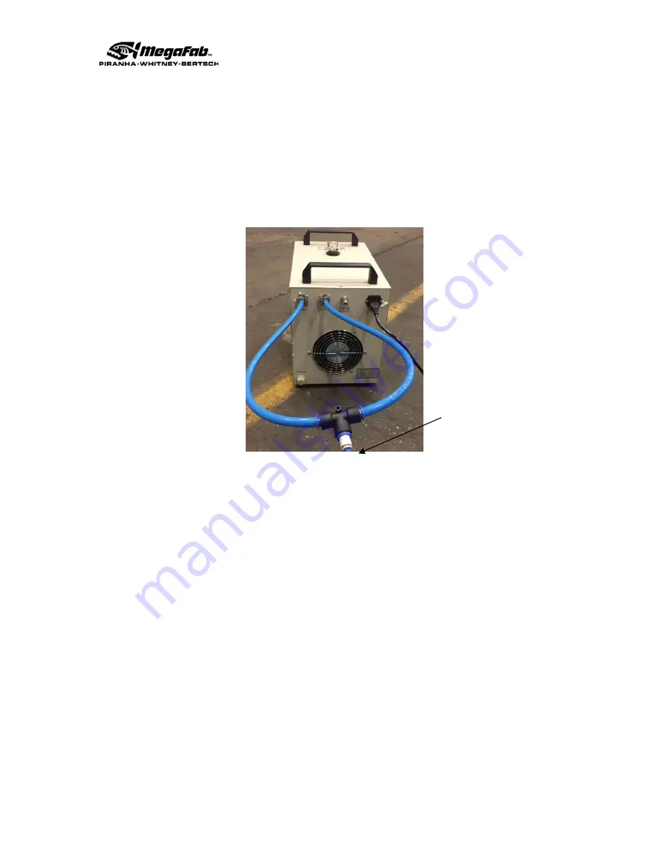
1. The inlet and outlet of the chiller must be connected together using 12 mm
tubing on both ends of the supplied tee fitting. Connect the outlet of the tee
fitting to the water solenoid located next to the incoming air regulator on the
machine using 8 mm tubing. DO NOT CONNECT THE INLET OF THE
CHILLER TO A WATER SUPPLY.
2. Bend the copper tubing so that the end of the tubing aims slightly below the
nozzle of the torch.
3. Fill the water resevoir from the fill port on top of the chiller.
4. The chiller is now ready to use.
To Water Solenoid
Summary of Contents for CNC Plasma Cutting Table
Page 2: ......
Page 4: ...TABLE OF CONTENTS Sept 2018 4...
Page 22: ...SAFETY Sept 2018 22...
Page 24: ...INSTALLATION Sept 2018 24...
Page 88: ...PROGRAMMING Sept 2018 88...
Page 117: ...PIPE CUTTING ATTACHMENT Sept 2018 117 Pipe Supports Pipe Cutter Base...
Page 124: ...PIPE CUTTING ATTACHMENT Sept 2018 124...
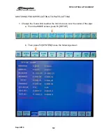
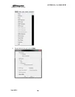
Page 128: ...PIPE CUTTING ATTACHMENT Sept 2018 128 j Then press F2 SYSTEM to see the following...
Page 136: ...PIPE CUTTING ATTACHMENT Sept 2018 136...
Page 140: ...WATER MIST CHILLER Sept 2018 140...
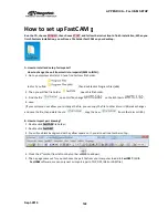
Page 144: ...APPENDIX A FastCAM SETUP Sept 2018 144 4 Choose the functions you need and Enter...
Page 154: ...APPENDIX A FastCAM SETUP Sept 2018 154...
Page 159: ...APPENDIX A FastCAM SETUP Sept 2018 159...
Page 164: ...APPENDIX A FastCAM SETUP Sept 2018 164...
Page 170: ...APPENDIX B Parametric Shape Library Sept 2018 170 9 Fla X 10 Lad 11 Rec 12 Rec8...
Page 172: ...APPENDIX B Parametric Shape Library Sept 2018 172 19 Rec 20 Rec c 21 Circle4 22 Rec...
Page 174: ...APPENDIX B Parametric Shape Library Sept 2018 174...

