INSTALLATION
Sept-2018
36
3.3.
Installing Covers (5’ X 10’ only)
To meet the transportation regulations of load size, the motor covers are not
pre-installed to the machine for shipment. The following procedure can be
followed to install motor covers:
1. Locate both motor covers, 1 for each side. The picture below shows the
cover for the motors. The cover for the cable carrier side has an extra
bracket attached to it.
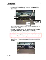
2. Take the cable carrier side cover and place it over the motor. Ensure
that cables are routed under the bracket as shown in the picture below.
3. Align the side holes and Install M6 button head cap screw on each side
of the 2 holes. Then align the holes on the bracket and install the M6
socket head cap screw to attach the cable carrier with the cover bracket.
4. Repeat the above procedure for the other side.
Motor
Cover
Motor Cover
cable carrier
side
Bracket
Summary of Contents for CNC Plasma Cutting Table
Page 2: ......
Page 4: ...TABLE OF CONTENTS Sept 2018 4...
Page 22: ...SAFETY Sept 2018 22...
Page 24: ...INSTALLATION Sept 2018 24...
Page 88: ...PROGRAMMING Sept 2018 88...
Page 117: ...PIPE CUTTING ATTACHMENT Sept 2018 117 Pipe Supports Pipe Cutter Base...
Page 124: ...PIPE CUTTING ATTACHMENT Sept 2018 124...
Page 128: ...PIPE CUTTING ATTACHMENT Sept 2018 128 j Then press F2 SYSTEM to see the following...
Page 136: ...PIPE CUTTING ATTACHMENT Sept 2018 136...
Page 140: ...WATER MIST CHILLER Sept 2018 140...
Page 144: ...APPENDIX A FastCAM SETUP Sept 2018 144 4 Choose the functions you need and Enter...
Page 154: ...APPENDIX A FastCAM SETUP Sept 2018 154...
Page 159: ...APPENDIX A FastCAM SETUP Sept 2018 159...
Page 164: ...APPENDIX A FastCAM SETUP Sept 2018 164...
Page 170: ...APPENDIX B Parametric Shape Library Sept 2018 170 9 Fla X 10 Lad 11 Rec 12 Rec8...
Page 172: ...APPENDIX B Parametric Shape Library Sept 2018 172 19 Rec 20 Rec c 21 Circle4 22 Rec...
Page 174: ...APPENDIX B Parametric Shape Library Sept 2018 174...

