INSTALLATION
Sept-2018
43
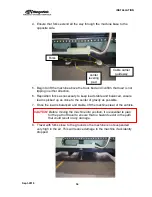
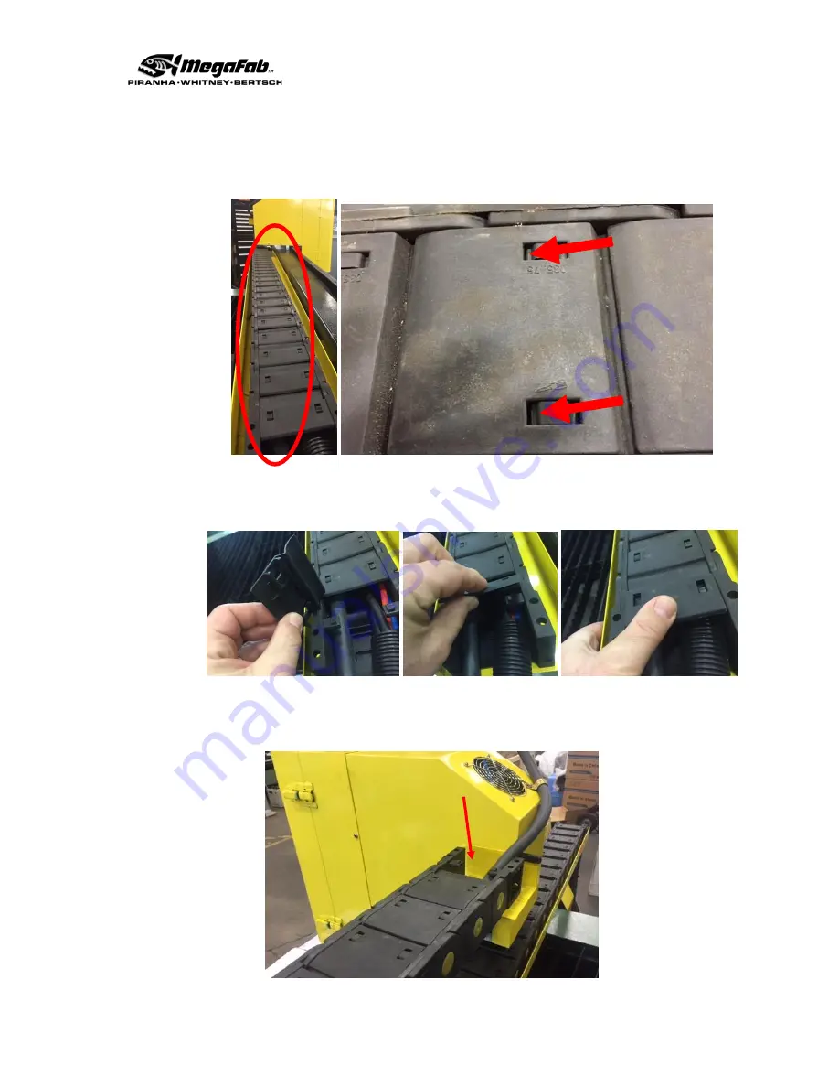
4. Expose the top side of the cable carrier by removing the plastic covers.
Use a screwdriver to unsnap the plastic covers by gently prying up in the
slots provided.
5. After running the torch leads, snap the plastic covers back in place. Take
care to make sure that each cover is fully snapped in place.
Leave off the last plastic clip as the torch lead exits each cable carrier
(this will give the torch lead a more generous radius as it exits the cable
carrier.
Summary of Contents for CNC Plasma Cutting Table
Page 2: ......
Page 4: ...TABLE OF CONTENTS Sept 2018 4...
Page 22: ...SAFETY Sept 2018 22...
Page 24: ...INSTALLATION Sept 2018 24...
Page 88: ...PROGRAMMING Sept 2018 88...
Page 117: ...PIPE CUTTING ATTACHMENT Sept 2018 117 Pipe Supports Pipe Cutter Base...
Page 124: ...PIPE CUTTING ATTACHMENT Sept 2018 124...
Page 128: ...PIPE CUTTING ATTACHMENT Sept 2018 128 j Then press F2 SYSTEM to see the following...
Page 136: ...PIPE CUTTING ATTACHMENT Sept 2018 136...
Page 140: ...WATER MIST CHILLER Sept 2018 140...
Page 144: ...APPENDIX A FastCAM SETUP Sept 2018 144 4 Choose the functions you need and Enter...
Page 154: ...APPENDIX A FastCAM SETUP Sept 2018 154...
Page 159: ...APPENDIX A FastCAM SETUP Sept 2018 159...
Page 164: ...APPENDIX A FastCAM SETUP Sept 2018 164...
Page 170: ...APPENDIX B Parametric Shape Library Sept 2018 170 9 Fla X 10 Lad 11 Rec 12 Rec8...
Page 172: ...APPENDIX B Parametric Shape Library Sept 2018 172 19 Rec 20 Rec c 21 Circle4 22 Rec...
Page 174: ...APPENDIX B Parametric Shape Library Sept 2018 174...

