OPERATIONS
Sept-2018
67
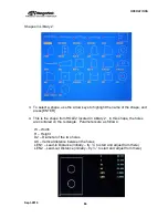
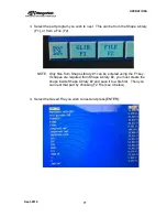
5. Select each parameter by using the up and down arrow keys. After each
parameter is changed, press the [ENTER] key. Once the changes are made,
press F7 [APPLY] and the geometry will update to the new values.
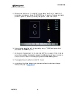
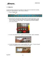
6. Once you are satisfied with the geometry, press F8 [OK] and you will be
directed to the HOME screen.
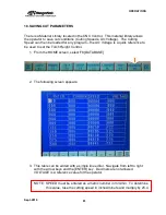
7. At this point, the geometry of the part has NOT been saved. While it can be
run on the machine, it cannot be nested, modified, or used later. In order to
save it, see the section on Editing Programs and File Management.
8. The program can now be run in AUTO mode.
9. A complete list of the shapes and parameters for the parametric shape
libraries is found in
Appendix B
.
Summary of Contents for CNC Plasma Cutting Table
Page 2: ......
Page 4: ...TABLE OF CONTENTS Sept 2018 4...
Page 22: ...SAFETY Sept 2018 22...
Page 24: ...INSTALLATION Sept 2018 24...
Page 88: ...PROGRAMMING Sept 2018 88...
Page 117: ...PIPE CUTTING ATTACHMENT Sept 2018 117 Pipe Supports Pipe Cutter Base...
Page 124: ...PIPE CUTTING ATTACHMENT Sept 2018 124...
Page 128: ...PIPE CUTTING ATTACHMENT Sept 2018 128 j Then press F2 SYSTEM to see the following...
Page 136: ...PIPE CUTTING ATTACHMENT Sept 2018 136...
Page 140: ...WATER MIST CHILLER Sept 2018 140...
Page 144: ...APPENDIX A FastCAM SETUP Sept 2018 144 4 Choose the functions you need and Enter...
Page 154: ...APPENDIX A FastCAM SETUP Sept 2018 154...
Page 159: ...APPENDIX A FastCAM SETUP Sept 2018 159...
Page 164: ...APPENDIX A FastCAM SETUP Sept 2018 164...
Page 170: ...APPENDIX B Parametric Shape Library Sept 2018 170 9 Fla X 10 Lad 11 Rec 12 Rec8...
Page 172: ...APPENDIX B Parametric Shape Library Sept 2018 172 19 Rec 20 Rec c 21 Circle4 22 Rec...
Page 174: ...APPENDIX B Parametric Shape Library Sept 2018 174...

