

Installer Note:
Please make sure that these instructions are left with the customer.
©2019 PIRIT
®
HEATED PRODUCTS, WRAP-ON
WRAP ON ROOF AND GUTTER DE-ICING CABLE FOR METAL OR
PLASTIC/VINYL GUTTERS AND DOWNSPOUTS
Please read through all instructions before installation begins. Proper preparation and planning will assure a correct and trouble free installation.
CAUTION:
• This cable has been designed and manufactured and the instructions have been written for the sole intended use of preventing the formation
of ice dams upon pitched roofs with non-combustible tab shingles, in gutters and in downspouts.
• Always directly connect cable to 120 V, weatherproof outlet with proper grounding. Use only watertight construction or enclosures Type 3, 3S,
4, 4X or 6P junction box when installing.
• Make certain the gutters and downspouts are free of leaves and other debris prior to the winter season.
• Do not allow cable to overlap or crisscross.
• Cable contains NO serviceable parts and cannot be altered in length. Any attempt to physically alter the cable will void the warranty.
TESTING THE CABLE:
Uncoil cable completely and lay out on the ground. Do not allow the cable to touch itself. Plug the cable in and wait approximately 5 minutes. Cable
should feel slightly warm to the touch.
INSTALLATION INSTRUCTIONS
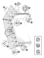
1. Begin the installation process by determining the portions of the roof where snow and ice may accumulate. Plan to install the roof and gutter
cable in all gutters and down all downspouts. This wilt maintain a path for melted water to flow. Structures without eaves may find this amount
of protection to be sufficient. For structures with eaves, plan to form the cable into a series of triangles along the roof. The peak of each triangle
should be the width of the eave plus one foot (See Figure 2A), with the base of the triangle forming a drip loop that is extended into the gutter
to allow water to flow off of the roof (See Figure 2B). Allow one to two feet between triangles (See Figure 2C). Additional height along the roof
and/or closer spacing may be required near valleys or dormers where snow and ice tend to accumulate.
2. Use care when working upon the roof or along the gutters of any structure in order to avoid personal injury. Be alert to the possible danger from
power lines and tree branches which may be in the vicinity. Be sure that the ladder has secure footing placement. Once a safe working condition
has been established, begin to mark the spacing of each triangle with a chalk mark on the roof. After this has been completed, carefully begin
to attach the provided aluminum clips along the planned route. The points on each clip are designed to penetrate asphalt type shingle material.
Slide the clip under the edge of a shingle, force the shingle down over the points and bend the points over to secure the clip in place (See Figure
2D). Continue this process along the planned route. If a triangle extends further than three feet, use a clip at the mid-point.
3. Begin the cable installation at the outlet box. The outlet box shall be a permanently installed, weatherproof, properly grounded receptacle having
GFCI protection. Install the outlet box under the eaves. Arrange the power condition so that the cordset (the portion of the cable with the three prong
plug) approaches the outlet from below, forming a drip loop, so that water will not run down the cord to the plug and into the outlet (See Figure 2E).
4. Extend the cable along the roof following the triangle patterns laid out Route the cable carefully so as to avoid abuse from a ladder or other
object. With a gloved hand, press (or curl) the open end of the aluminum clip down over the roof and gutter cable sufficient to hold the cable
tn position. Do not pound tile clips with a hammer as this may damage the cable. Use caution to press the clip firm but not to cut the cable or
outer Jacket in any way. Repeat this procedure along the entire length of the roof. Remember to form a drip loop into the gutter at the end of
each triangle (See Figure 2B).
5. The roof and gutter cable is now secured to the roof. Lay the remaining cable into the gutter and proceed with the installation. If, after securing
the cable to the roof, no additional cable is available, you must begin a second run of cable in the gutter.
6. The cable shall be laid in the bottom of the gutter (See Figure 2B) and down each downspout along the run. For downspouts in the middle of a
cable run, extend the cable down and then back up the same downspout, making sure to affix cable spacers every 6-8 inches to prevent the
cable from coming in contact with itself (See Figure 2F). At the end of the installation, extend the tail to the cable to the end of the downspout,
allowing it to protrude slightly from the opening so that the melting water can flow. Protect all cable that protrudes past the lower opening of
the downspout
7. Carefully recheck the installation to be sure all clips are fastened securely and that the cable has not come in contact with itself at any point,
especially in the downspout. If an excess of cable remains, you may extend a few of the triangles on the roof to compensate. If a small amount
of additional cable is needed, you may shorten a few of the triangles in an area having fess need.
DO NOT ATTEMPT TO SHORTEN, CUT OR
SPLICE THE ROOF AND GUTTER CABLE.
Two copies of a caution notice indicating the presence of electric de-icing and snow-melting equip-
ment on the premises are packed with this unit. One notice must be posted at the fuse or circuit-breaker and the other on or next to the on/off
control for the cable unit Both notices must be clearly visible.
8. If the power cord is shortened cordtag with cable information must be retained.


