No Diving or Jumping. Observe all Safety Rules
4-3
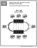
GENERAL INSTRUCTIONS - BRACELESS OVAL POOLS
ASSEMBLING THE POOL FRAME
Section
4
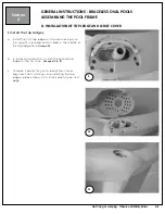
B. INSTALLATION OF ANCHOR PINS ON TOP LEDGE
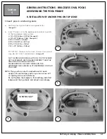
1. Insert pins in anchoring slots
a. Each anchoring slot has an assigned letter.
(
Image 5)
b. Insert the pins into the appropriate anchoring slots
of the top ledge index system.
A : 12' x 19' (3,66m x 5,93m); (Image 6)
A : 12’ x 23’ (3,66m x 7,11m); (Image 6)
B: 15' x 22' (4,57 x 6,86m)
B: 15’ x 26’ (4,57m x 8,00m)
B: 15’ x 30’ (4,57m x 9,14m)
C: 18’ x 33’ (5,49m x 10,16m)
IMPORTANT: Make sure to insert the pin the correct
way, do not insert upside down.
(Image 8)
N.B: THE PINS ANCHORING SLOTS ON THE TOP LEDGES
OF THE STRAIGHT SECTION ARE DIFFERENT THAN THE
ONES FOR THE ROUND SECTION.
PLEASE REFER TO THE NEXT PAGES FOR THE
APPROPRIATE ANCHORING SLOTS DEPENDING ON YOUR
POOL SIZE.
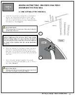
NOTE: This pool has a built in adjustment at each
upright. At each ledge junction you can move left
or right by 1/2 an inch (1.25cm).
Do not tighten the ledges to final setting, install all
ledges and then go back and adjust accordingly.
5
6
8
7
WRONG WAY


