8
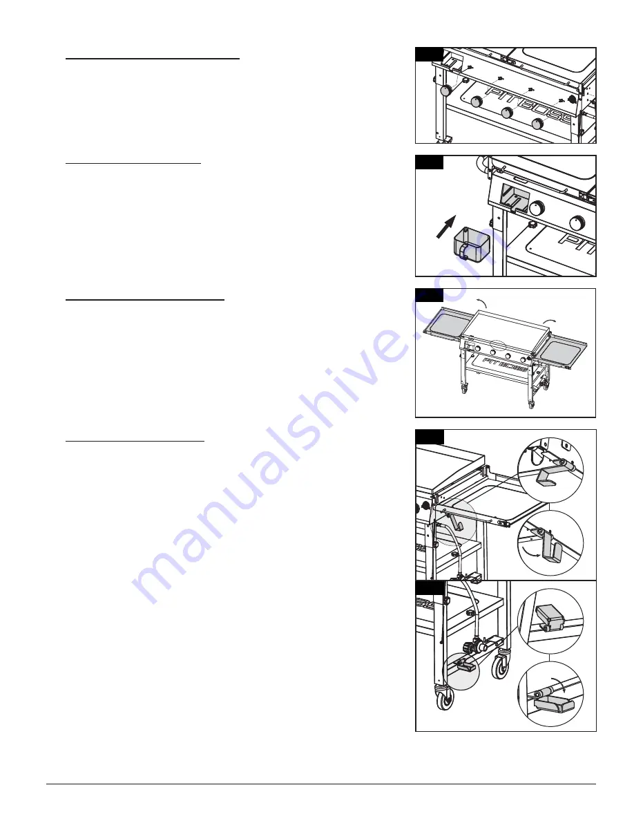
9. SET-UP FOR GAS CYLINDER
Installation:
• Drop the upper gas cylinder hook into the correct position for usage.
Note steps as shown in illustration 9A.
• Unfold the lower gas cylinder bracket into the correct position for
usage. Note steps as shown in illustration 9B.
• The unit is now completely assembled.
8. EXPANDING THE SIDE SHELVES
Installation:
• Unlock the front latch. Unfold the side shelves to expose the hot plate
for usage.
6. MOUNTING THE CONTROL KNOBS
Parts Required:
4 x Control Knob
(#4)
Installation:
• Mount each Control Knob to the front panel of the unit.
7. PLACING THE GREASE CUP
Parts Required:
1 x Grease Cup
(#3)
Installation:
• On the front of the unit, place the Grease Cup into the Grease Cup
housing, as shown in the illustration.
7
6
9A
9B
8
4
4
4
4
3


