


C-2
SV61831 Rev. A DA50S/DA55S/DA70S/DA75S AddressRight™ Printers Service Manual
Appendix C • Schematics
D(0:31)
A(0:25)
CS2~
CS4~
CS5~
RD/WR~
RAS~
RD~
WE0~ WE1~
WE2~
WE3~
RESM~
TMS
TDO
COM2_RXD
COM2_TXD
COM1_TXD
COM1_RXD
DACK0
DREQ0~
RST_SYS~
TRST
FWE
CKIO
BS~
CS0~
LED1_RED LED2_RED
PFO~
LCLK
CS6~
IRQ4~
TRANSPORT_CL~
CABLE_n
COLOR_n
MODEL13K_n
WDT_CP
LED3_GRN LED4_GRN
XL_PD(0:7)
FPGA_DONE
FPGA_RES
TDI
IRQ5~
IRQ7~
IRQ6~
B_R10X_BUF
B_TSR_BUF
C_R10X_BUF
C_TSR_BUF
CS3~
CS1~
CKE
TCK
ASEBRK-/BRKACK
IRL0~
IRL1~ IRL2~
IRL3~
INIT_FPGA~
PROG_FPGA~
CCLK_FPGA
BREQ~
RDY~
CFG2
I2C0_SCL
I2C0_SDA
CFG1
RST_SYS~
D(31)
D(30)
D(29)
D(28)
D(27)
D(26)
D(25)
D(24)
D(23)
D(22)
D(21)
D(20)
D(19)
D(18)
D(17)
D(16)
D(15)
D(14)
D(13)
D(12)
D(11)
D(10)
D(9)
D(8)
D(7)
D(6)
D(5)
D(4)
D(3)
D(2)
D(1)
D(0)
A(1)
A(3) A(4) A(5)
A(6) A(7)
A(8) A(9) A(10)
A(11) A(12) A(13)
A(14) A(15)
A(16) A(17) A(18)
A(19) A(20)
A(21) A(22) A(23)
A(24) A(25)
A(0)
A(2)
C98
0.1uF
C100
0.1uF
C126
0.01uF
C99
0.1uF
C125
0.01uF
C102
0.1uF
C128
0.01uF
C101
0.1uF
C127
0.01uF
C104
0.1uF
C130
0.01uF
C103
0.1uF
C129
0.01uF
C106
0.1uF
C132
0.01uF
C105
0.1uF
C131
0.01uF
C108
0.1uF
C134
0.01uF
C107
0.1uF
C133
0.01uF
C110
0.1uF
C136
0.01uF
C109
0.1uF
C135
0.01uF
C112
0.1uF
C138
0.01uF
C111
0.1uF
C137
0.01uF
C114
0.1uF
C140
0.01uF
C151
47uF
C150
47uF
ALL
RESISTORS
ARE
IN
OHMS,
+/-.5
AND
1/10
WATT.
ALL
CAPACITANCE
ARE
I
N
u
f
(MICROFARAD).
2.
FOR
ASSEMBLY
DRAWING
SEE
DRAWING
NOTES:
1.
UNLESS
OTHERWISE
SPECIFIED:
(2)
(3)
(3)
(4)
(2),(4)
(2)
(2),(2),(3),(4)
(2),(3),(4)
(2),(4)
(2),(4)
(2),(4)
(2),(4)
(2)
R161
10Kohms
R158
10Kohms
R159
10Kohms
R162
10Kohms
R160
10Kohms
C16
0.1uF
261-1412
2
1
J1
(4)
(3)
(4)
(3)
C82
30pF
C81
30pF
(5)
(5)
(5)
(5)
(3)
(3)
(3)
3
4
(9)
R147
10Kohms
R145
10Kohms
Page:
01
of
10
Time:04:31:34
PM
Date:04/06/2006
DWG
NO.
and
is
not
to
be
copied.
Inc.
and
contains
PROPRIETARY
and
CONFIDENTIAL
information
This
document/data
record
is
the
property
of
Pitney
Bowes
LOC
S
Y
M
CHANGE
D
ESCRIPTION
C
H
K
BY
DATE
C.O.
NO.
2
1
2
3
4
1
D
Pitney
Bowes
WORKMANSHIP
PER
PB
PROCEDURE
B1850
UNLESS
OTHERWISE
SPECIFIED:
TOLERANCES
0.03
0.01
0.005
ONE
PLACE
DECIMALS
TWO
PLACE
DECIMALS
THREE
PLACE
DECIMALS
+ -
-
-
+
+
CLASSIFICATION
OF
CHARACTERISTICS
PER
P
B
B1525
CRITICAL
MAJOR
MINOR
ALL
OTHER
CHARACTERISTICS
DWG
SIZE
DO
NOT
SCALE
T
HIS
DRAWING
PROJECTION
THIRD
ANGLE
REQ
NEXT
ASSEMBLY
PRODUCT
CODECHANGE
ORDER
NO
SCALE
DATE
PART
NO
MODEL
TITLE
APPROVED
DRAWN
DATE
NONE
(2)
R277
33ohms
R113
1Kohms
(4)
C124
0.01uF
(5)
(5)
(5)
(5)
(5)
(5)
WW
POST
TP22
Black
TP29
Yellow
TP31
J12
1
9
13
2
11
5
6
14
7
8
10
12
27
S1
18
SWITCH
45
36
R167
10Kohms
R346
10Kohms
R352
10Kohms
R342
10Kohms
R341
10Kohms
R345
10Kohms
R355
10Kohms
R354
10Kohms
R351
10Kohms
R306
10Kohms
R150
10Kohms
R304
10Kohms
R148
10Kohms
R152
10Kohms
R337
10Kohms
R155
10Kohms
R143
10Kohms
R340
10Kohms
R165
10Kohms
R142
10Kohms
R350
10Kohms
R144
10Kohms
R349
10Kohms
R72
10Kohms
R387
10Kohms
WW
POST
TP15
WW
POST
TP19
WW
POST
TP14
WW
POST
TP13
WW
POST
TP20
WW
POST
TP23
WW
POST
TP21
WW
POST
TP12
WW
POST
TP11
WW
POST
TP10
WW
POST
TP9
WW
POST
TP8
WW
POST
TP26
WW
POST
TP7
TP17
TP24
TP16
TP18
TP25
WW
POST
TP6
Black
TP30
Yellow
TP32
R163
10Kohms
(4),(9)
(6)
(5)
(5)
(5)
(9)
(2),(3),(4)
(4)
(4)
(4)
(4)
XL_PD(6)
XL_PD(4)
XL_PD(3)
XL_PD(1)
XL_PD(2)
XL_PD(7)
(4)
(4)
XL_PD(0)
XL_PD(5)
(4)
(4)
(4)
(7)
(7)
(7)
(7)
(2)
(2),(3),(4)
R343
10Kohms
R344
10Kohms
R347
10Kohms
R348
10Kohms
R146
10Kohms
C153
100pF
(9)
R422
4.7Kohms
R424
4.7Kohms
R425
4.7Kohms
R426
4.7Kohms
R430
4.7Kohms
R431
4.7Kohms
R432
4.7Kohms
R433
4.7Kohms
R434
4.7Kohms
R186
10ohms
R419
10Kohms
R421
10Kohms
R151
10Kohms
R149
10Kohms
R153
10Kohms
R154
10Kohms
R185
10ohms
R184
10ohms
R183
10ohms
C156
10uF
C155
10uF
C154
10uF
C93
0.1uF
J19
15
11
3
7
9
10
8
4
12
6
2
R418
10Kohms
R420
10Kohms
1
2
Y3
16.000
MHZ
200-1082
K19
L20
L19
L18
L17
C8
F4
E4
T3
E3
P19
R19
T19
P20
R20
T20
B8
A8
B9
A9
A18
D19
D1
C17
D18
E19
E20
A1
C2
D4
B6
A7
B7
A6
N20
N19
M20
M19
F19
F20
F17
F18
D16
D17
C16
B17
A17
G20
G19
H17
H18
P2
F2
G2
H2
J2
K2
L2
M2
N2
F1
G1
H1
J1
K1
L1
M1
N1
R1
P1
R2
T1
T2
D5
B10
C1
K20
J19
J20
H19
H20
B1
A15
B16
A16
B11
B14
B15
B13
B12
A10
A13
A14
A12
A11
A5
C5
B5
D2
C6
D3
D6
D8
C15
D12
C12
C10
D10
A20
B19
C20
D20
C18
E1
E2
A2
V1
4
V7
P1
8
P3
G1
8
G3
C1
4
C7
V1
8
V1
6
V1
2
V1
1
V1
0
V8
V5
V3
N1
8
M1
8
M3
K3
J1
8
H3
E1
8
C1
3
C1
1
C9
B2
0
A19
B3
A4
A3
K1
8
U1
4
U7
P1
7
P4
G1
7
G4
D1
4
D7
W1
9
W2
U1
6
U1
2
U1
1
U1
0
U8
U5
N1
7
M1
7
M4
K4
J1
7
H4
E1
7
D1
5
D1
3
D1
1
D9
C1
9
B1
8
C3
B4
B2
K1
7
U17
16
BIT
FLASH
MODE
3
LITTLE
ENDIAN
MFI
MODE
EXT
CRYSTAL
BGA256_20x20_1MM
HD6417760BP200ADV
HD6417760BP200ADV
VDD
VDDQ
VDD-PLL1
VDD-PLL2
VDD-PLL3
VDD-CPG
AVCC-ADC
VSS-PLL1
VSS-PLL2
VSS-PLL3
VSS-CPG
AVSS-ADC
VSSQ
VSS
AN3
AN2
AN1
AN0
ADTRG~/AUDATA(0)
CAN1_RX/AUDATA(3)
CAN1_NERR/AUDSYNC
CAN0_RX/AUDATA(2)
CAN0_NERR/AUDCK
HSP1_CS~/SIM_RST/MCCMD
HSP1_CLK/SIM_CLK/MCCLK
HSP1_TX/SIM_D/MCDAT
HSPI_RX
DREQ1~
DREQ0~
IRL3~
IRL2~
IRL1~
IRL0~
NMI
TRST~
TDI
TMS
TCK
USB_OVC~
UCLK
SCIF2_RXD
SCIF1_RXD
SCIF0_RXD
HAC_BIT_CLK1
HAC_BIT_CLK0
ASEBRK~/BRKACK
USB_DM
USB_DP
SCIF2_RTS~
SCIF2_CTS~
SCIF2_CLK
SCIF1_RTS~
SCIF1_CTS~
SCIF1_CLK
SCIF0_CLK
CMT_CTR3
CMT_CTR2
CMT_CTR1
CMT_CTR0/TCLK
SSI1_SDATA/HAC_SD_OUT1
SSI1_SCK/HAC_SD_IN1
SSI1_WS/HAC_SYNC1
SSI0_SDATA/HAC_SD_OUT0
SSI0_WS/HAC_SYNC0
SSI0_SCK/HAC_SD_IN0/BS2~
I2C1_SDA
I2C1_SCL
I2C0_SDA
I2C0_SCL
VEPWC/IRQ5~
VCPWC/IRQ4~
MFI-D15/LCD_DATA15
MFI-D14/LCD_DATA14
MFI-D13/LCD_DATA13
MFI-D12/LCD_DATA12
MFI-D11/LCD_DATA11
MFI-D10/LCD_DATA10
MFI-D9/LCD_DATA9
MFI-D8/LCD_DATA8
MFI-D7/LCD_DATA7/DRAK3/DACK3
MFI-D6/LCD_DATA6/DREQ3~
MFI-D5/LCD_DATA5/DRAK2/DACK2
MFI-D4/LCD_DATA4/DREQ2~
MFI-D3/LCD_DATA3/IRQ7~
MFI-D2/LCD_DATA2/IRQ6~
MFI-D1/LCD_DATA1
MFI-D0/LCD_DATA0
MFI-RW/LCD_FLM
MFI-RS/LCD_M_DISP
MFI-MD/LCD_CL2
MFI-E/LCD_CL1
MFI-CS~/LCD_DON
MFI-INT~/LCD_CLK
EXTAL
CA
BREQ~
RDY~
MRESET~
RESET~
MD8
MD7
MD6/IOIS16~
MD5
MD4/CE2B~
MD3/CE2A~
MD2
MD1
MD0
A0 A1
A2 A3 A4
A5 A6
A7 A8 A9
A10 A11 A12
A13 A14
A15 A16 A17
A18 A19
A20 A21 A22
A23 A24 A25
D0
D1 D2 D3
D4 D5 D6
D8
D7
D9
D10 D11
D12 D13
D14 D15 D16
D17 D18 D19
D20 D21
D22 D23 D24
D25 D26 D27
D28 D29
D30 D31 CS0~ CS1~ CS2~ CS3~ CS4~ CS5~ CS6~
RD/WR~
RAS~
RD~/CASS~/FRAME~
WE0~/DQM0/REG~
WE1~/DQM1
WE2~/DQM2/ICIORD~ WE3~/DQM3/ICIOWR~
CKIO
CKE
HAC_RES~
SCIF0_TXD
SCIF1_TXD SCIF2_TXD
USB_PENC
TDO
DACK0 DACK1
DRAK0 DRAK1
DCK
CAN0_TX/AUDATA(0) CAN1_TX/AUDATA(1)
RESERVED/AUDATA(3)
RESERVED/AUDATA(2) RESERVED/AUDATA(1)
RESERVED/AUDCK
RESERVED/AUDSYNC
BS~
BACK~
STATUS0
STATUS1
XTAL
(3)
2
1
U51
GROUND
=
GND
VCC
=
+3.3V
74LV14
4
3
U51
GROUND
=
GND
VCC
=
+
3.3V
C79
47uF
R455
7.5Kohms
CR21
BAT54S
WS92000
CO10336
YOUNG
LEE
WSXX
JOG
CCWS82000
RE
F
02/02/06
INITIAL
PRODUCTION
RELEASE
THIS
P
AGE:
1)
DO
NOT
POPULATE
R419
AND
R421
2)
REASSIGN
P
1
T
O
J1,
P19
T
O
J
19
AND
P6
TO
J12
3)
CHANGE
RESET
SYS
DELAY
VALUES
AND
SUBSTITUTE
BUFFER
FOR
TWO
U51
GATES.
DELETE
C80
AND
C77
KM
Y
L
Do
Not
P
opulate:
R419
and
R42
for
configuration
bits
=
0
0
INITIAL
BUILD
SECONDARY
BUILD
M
ODIFICATIONS
THIS
P
AGE:
1)
FIXED
REVERSED
PINS
W5
AND
Y5
ON
U17
SYMBOL
PB#
315-0313.
2)
CHANGE
USB
CHIP
SELECT
FROM
CS4-
TO
CS6-
B
01/08/06
YL
KM
CO10336
WSXX
WS92000
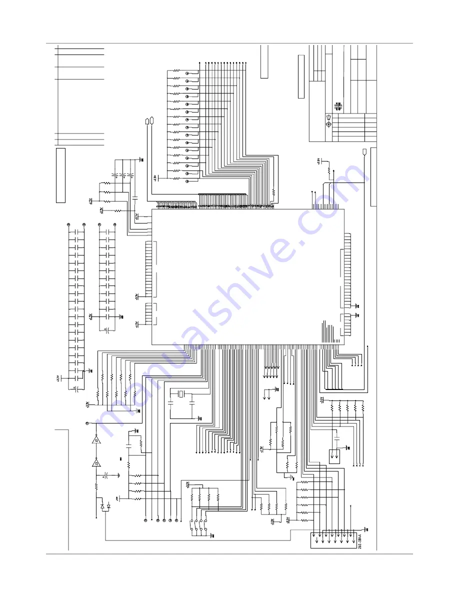
SCHEM,
MAIN
PROCESSOR
BD,
9K/13K
MAIN
PROCESSOR
MD[0,1,2]:
CLOCK
MODE
MD[3,4,6]:
CS0
BUS
WIDTH
MD[5]:
1=LITTLE
ENDIAN
MD[7]:
0=MFI
MODE
MD[8]:
1=INTERNAL
CLOCK
CONFIGURATION
CONTROL
DOCUMENT
REQUIRES
UPDATING
WHENEVER
THIS
DOCUMENT
IS
REVISED
KM
Y
L
12/26/05
A
JTAG
NOTE:
ALL
CRYSTAL
LAYOUT
CONNECTIONS
AS
SHORT
AS
POSSIBLE
NOTE:
PROCESSOR
D
ECOUPLING
MUST
BE
AS
CLOSE
T
O
EACH
P
IN
AS
POSSIBLE
WITH
SHORT
WIDE
TRACES
C
WS82000
D
YL
KM
04/05/06
CO11521
2/24/06
2/24/06
DESIGN
MODIFICATIONS:
-
NONE
THIS
PAGE
-


