DA80F/DA95F AddressRight™ Printers Service Manual (SV61962 Rev. A)
5-63
Removal and Replacement • 5
DA95F (WF96) - Printer Parts Removal
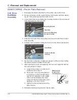
15. When installing the new print head (Newport) board, do the following:
• Ensure the two locator pins on the back side of the print head board
are aligned to the black print head stall.
Locator Pins
for Print Head
Board (Circled)
• When reassembling the bottom retainer plate, engage the tabs on
one side of the part to the print head stall and then pivot it into posi-
tion. The engagement tabs on the other side of the plate will “snap”
into position on the opposite side of the cartridge stall. Tighten the
screws lightly once plate has been snapped into position.
5.36 Print
Head Cables
and Print
Head Boards
(continued)
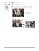
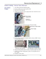
16. Attach (new) print head ribbon cables, starting at print head side. Apply a
light push to the cable while inserting to allow it to seat fully and straight
into the connector socket. Make sure the cable end is marked "PH" for
print head, and the black tab at the cable end is pointing upwards as it is
being inserted into the print head connector. After inserting cable, press the
tan locking piece inwards (toward the connector) to lock cable into place.
Tan Locking Piece Edge of Connector
Black Tab Facing Up
17. Route the three print head ribbon cables through clamping mechanism
(has tape on one side) and fasten clamp with cables to print head as-
sembly (one screw). Make sure there is enough slack (see right figure). A
very slight overlap of cables is OK when in final position.
Clamping
Mechanism
Tape
Cable Slack (circled)
Screw


