background image

A-16

DA80F/DA95F AddressRight™ Printers Service Manual (SV61962 Rev. A)

Appendix A  • Printer Control Panel Menus and Utilities

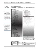
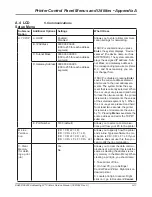
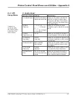
A.4  LCD 
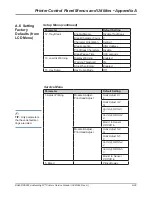
Setup Menu

TIP:

 For keeping the 

nozzles clear and 
functioning properly for 
most jobs, we suggest 
you enable:

“Pre-Purge at Start” 
“Nozzle Keep Alive” 

OR

if the quality of the 
piece is of the utmost 
importance, you may 
enable:

“Periodic Purge” 
“Purge Interval” 

Do 

not

, however, en-

able both of these 
together (i.e, “Periodic 
Purge” and “Nozzle 
Keep Alive”) because 
it will waste ink, affect 
throughput, and may 
produce smudging.

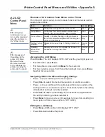
Sub-menu option

Settings

What It Does

A. Pre-Purge at 
Start

Enable,      
Disable

Allows you to enable and disable the perfor-
mance of print head maintenance cycles at 

the start of job runs

. The maintenance cycle 

consists of moving the print heads to the 
maintenance station, firing all the nozzles on 
the ink cartridges into an ink reservoir, and 
then wiping the heads.

B. Periodic Purge

Enable,      
Disable

Allows you to enable and disable the per-
formance of print head maintenance cycles 

during print jobs

. The maintenance cycle 

consists of moving the print heads to the 
maintenance station, firing all the nozzles on 
the ink cartridges into an ink reservoir, and 
then wiping the heads.

C. Purge Interval

20 - 300 
seconds (in 20 
second incre-
ments)

When initially viewed, this displays the de-
fault time period (in seconds) between print 
head maintenance cycles when running a 
job,


if “Periodic Purge” is enabled. The de-

fault settings are based on the print quality 
selected for your job: Executive quality is set 
for 120 seconds between cycles, Letter is 
set for 180 seconds, Draft is set at 240 sec-
onds, and Super Draft at 300 seconds. You 
may override the default and lengthen the 
time between cycles in an effort to increase 
throughput or save some ink (both minimally).

D. Nozzle Keep 
Alive

Enable,      
Disable

If set to “Enable”, the printer uses a random 
pattern of spitting to keep nozzles clean 
throughout the running of a job.

10.    Pre-Purge

Summary of Contents for DA80F

Page 1: ...Service Manual DA80F and DA95F AddressRight Fixed Head Printers DA80F WF81 DA95F WF96 ...

Page 2: ... Ca nadian Department of Communications Le present appareil numerique n emet pas de bruits radioelectriques depassant les limites appli cables aux appareils numeriques de la class A prescrites dans le Reglement sur le brouillage radio electrique edicte par le ministere des Communications du Canada NOTE This equipment has been tested and found to comply with the U S Standard for Safety UL1950 Third...

Page 3: ...s 2 1 2 3 Physical Equipment Specifications 2 2 2 4 Print Specifications 2 3 2 5 Material Specifications 2 7 Chapter 3 Theory 3 1 Changes From Earlier Models 3 1 3 2 Printer Architecture 3 2 3 3 Operating Sequence 3 6 Chapter 4 Troubleshooting Diagnostics 4 2 Block Diagrams 4 2 4 3 Main Controller Board Diagnostics 4 4 4 4 Error Codes 4 9 4 5 Print Samples for Troubleshooting 4 12 4 6 Feeding Issu...

Page 4: ...1 Feed Roller Pulley and Feed Roller Assembly 5 14 5 12 Feed Motor Assembly and Encoder Harness Assembly 5 16 5 13 Transport Motor Assembly 5 18 5 14 H Block Assembly Media Separators 5 20 5 15 Print Head Cables and Print Head Boards 5 21 5 16 Entry Idler Roller Arm 5 28 5 17A Feed Deck 5 30 5 17B Front Plate Assembly 5 32 5 18 Transport Metal Grit Roller 5 34 5 19 Exit Rubber Roller 5 35 5 20 Pow...

Page 5: ...ler Roller Support Module B Assembly 5 58 5 36 Print Head Cables and Print Head Boards 5 59 5 37 Belt Drive Assembly 5 67 5 38 Media Belts 5 69 5 39 Encoder Assembly 5 71 5 40 Drive Belt Motor Assembly 5 74 5 41 Power Supply 5 75 Chapter 6 Adjustments 6 1 List of Adjustments 6 1 Adjustments for All Models 6 2 LCD Display 6 2 6 3 Feeder Sensor Test and Calibration 6 2 DA80F WF81 Adjustments 6 4 Lev...

Page 6: ...6 Updating Firmware A 26 Appendix B Printer Communications B 1 Communication Scenarios B 1 B 2 Troubleshooting Tables B 4 B 3 Testing Printer Communications Within a Network B 6 Appendix C Schematics Main Processor Board for Both Printers C 2 DA80F WF81 Printer Block Diagram C 3 DA95F WF96 Printer Block Diagram C 4 Appendix D Print Head Alignment D 1 Reason for this Appendix D 1 D 2 Print Head Ali...

Page 7: ...or Setting up a DAxxx Series Printer Using the AddressRight Printer Control Panel Application SV61986 For other information on the printers refer to these sources Software Control Panel Application on the host PC see the help sys tem on the software FAQs document see the Customer Service website under the product page for AddressRight printers Training see Enhanced AddressRight Fixed Head Printers...

Page 8: ...ice people or equipment operators it is important to explain safety precautions to your students and encourage safety awareness 1 4 Safety Warning messages appear throughout this manual to alert you to potentially hazardous conditions Two designations indicate their relative seriousness WARNING Calls attention to improper practices that could result in a potentially serious even lethal injury to y...

Page 9: ...en fuse If a hot wire shorts to an ungrounded frame the frame itself becomes hot and poten tially dangerous A fuse is a weak link in a circuit designed to break down before anything else does The maximum safe current in a circuit is de termined by the designers Too large a fuse can pass excessive current damaging expensive equipment For electrical fires use Type C BC or ABC extinguishers only Don ...

Page 10: ...e careful of rugs even a few steps can recharge you Re ground your self whenever you ve walked away and returned to the machine Rugs are a major source of static buildup in the body Take greater precautions as the objects you handle get smaller A board in the machine is better protected than one that is not plugged in a chip on a board is better protected than one in your hand Stay away from metal...

Page 11: ...es cable are supplied with the printer If the customer chooses to use another USB cable it must be no longer than 15 feet 5 meters Windows 2000 SP4 Windows XP Pro SP2 Windows Server 2003 SP1 w latest Service Pack and Windows Vista Dot Net v2 0 5MB Disk space Administrative rights to install software Physical Dimensions DA80F 17 9 455mm high 18 5 470mm wide 17 7 450mm deep DA95F 15 380mm high 24 60...

Page 12: ... C Shipment Conditions Temperature Printer 4 to 140 F 20 to 60 C Humidity Supplies 5 to 85 Maximum Wet Bulb Temperature 85 F 29 C Noise Level DA80F The sound pressure level at the operator s position for this equipment as mea sured in any mode using ANSI and ISO Standards is no more than 75 dB A DA95F The sound pressure level at the operator s position for this equipment as mea sured in any mode u...

Page 13: ...rcode Characteristics Print Quality Barcode Printing Position The printer can print a barcode in one of three positions Above the address block Below the address block Print Modes Print Resolution The printers have four print resolutions they are Executive 600 DPI Letter 300 DPI Draft 200 DPI and Super Draft 150 DPI which represent the horizontal density Additionally there are two Light Mode setti...

Page 14: ...ir customers invoices When the invoices are mailed back in their return envelope the USPS sorts and processes this mail according to what version of FIM barcode is used on the envelope FIM A Postage required POSTNET bar code included FIM C Postage prepaid POSTNET bar code included and FIM D Postage re quired POSTNET bar code not included One of the requirements of the FIM barcode is that it needs ...

Page 15: ...3 head capacity DA95F 6 head capacity This Side Prints This Side Prints Feed Edge feeds into printer Feed Edge feeds into printer Flap down close to operator Example of Normal Orientation Flap down close to operator Flap down and away from operator This Side Prints This Side Prints Feed Edge feeds into printer Feed Edge feeds into printer Example of Inverted Orientation Flap down and away from ope...

Page 16: ...2 1 2 degrees Recommended Usage The printers have been tested under many different conditions Use of the printer should fall within these piece usage recommendations Monthly Piece Usage Product Life Typical Maximum DA80F 176 000 240 000 5 years or 14 400 000 cycles whichever comes first DA95F 480 000 1 000 000 5 years or 60 000 000 cycles whichever comes first NOTE Usage beyond the maximum monthly...

Page 17: ...roughput DA80F 22 000 envelopes hour DA95F 30 000 envelope per hour Based on Super Draft mode print quality 3 line destination address 18 characters per line 12 point character size Time New Roman font NOTE Adding graphics and or printing at a higher resolution e g Draft Let ter Executive mode will decrease throughput 2 4 Print Specifications 2 5 Material Specifications Media Sizes DA80F DA95F Min...

Page 18: ... 90 degrees with respect to the feed edge Material that is too stiff will cause feed prob lems Postcards have no folds or bends The printable side may have a higher surface roughness than the non printable side Self mailers may be of C Z or half folded construction They may not exceed the maximum allowable thickness as specified on the previous page and must be tabbed per postal regulations Half f...

Page 19: ... Glossy Paper this is material whose surface frictions falls outside the guidelines given here and in chart below Material shall not slide when placed on a 18 slope 10 2 degrees Envelopes shall not slide when placed on a 33 slope 18 2 degrees Material shall slide when placed on a 70 slope 35 degrees To test material for proper surface friction a clipboard is ideal for this test 1 Secure bottom pie...

Page 20: ...4 324mm 229mm ENV_C5 Envelope C5 229mm 162mm ENV_C6 Envelope C6 162mm 114mm ENV_C65 Envelope C65 229mm 114mm PG_ENV_C76 Envelope C76 162mm 81mm PG_ENV_C7 Envelope C7 114mm 81mm ENV_DL Envelope DL 220mm 110mm ENV_DLX Envelope DLX 235mm 120mm ENV_DLE Envelope DLE 225mm 114mm A4 A4 210mm 297mm A5 A5 148mm 210mm Asian Envelope Paper Sizes Envelope 12JE 140mm 265mm Envelope 9JE 190mm 265mm Envelope 6JE...

Page 21: ... also adding more diagnostic and administrative features Control panel menu supports bulk cartridge ink management low ink warning now works when using these types of cartridges Removed large transformer and replaced with heavier duty power supply allows a graceful shutdown of the printer and for the software parameters to be saved Same supply as used in DA5xx DA7xx shuttle head printers Print hea...

Page 22: ... midrange DM series mailing machines System Controller The system controller is comprised of the overall op erating system in the firmware that controls the behavior of the system and coordinates activities between the other sections User Interface The user interface is the LCD display the buttons and the software to drive it within the firmware Feeder and Transport Motion Control The feeder and t...

Page 23: ... 5 Piece 1 Piece 3 Piece 2 Exit Sensor Feeder Sensor Print Sensor Module B Printing Module A Printing Model WF96 Material 10 Envelope Throughput 32230 Cycle Time 0 112 pcs hr sec Timing Diagram 10 000 0 000 10 000 20 000 30 000 40 000 50 000 60 000 0 0000 0 1000 0 2000 0 3000 0 4000 0 5000 0 6000 0 7000 Time Values 2 5 2 1 5 1 0 5 0 0 5 1 1 5 Piece 1 Piece 3 Piece 2 Feeder Sensor Print Sensor Modu...

Page 24: ...tem _ minus Decrements a value Moves backwards through a choice list Negative response to query Menu Enters the menu system when OFF LINE Exits a submenu Enter Selects and or saves the displayed value Causes system to perform described action Advances to next screen plus Increments a value Moves forward through a choice list Affirmative response to a query Test Env Prints a test piece when OFF LIN...

Page 25: ...ional design of the h block media separator is to restrict all but the bottom piece of media The feed roller moves the piece of media between the entry idler rollers and the transport rollers The speed differential between the transport rollers and the feed rollers will create a gap between the moving pieces The feeder photo sensor assembly is energized as the piece of media is pushed out The tran...

Page 26: ...3 6 DA80F DA95F AddressRight Printers Service Manual SV61962 Rev A 3 Theory ...

Page 27: ...ollowing standard printer setup procedures in the order given There is a high likelihood that performing these procedures will correct the error If these procedures do not correct the problem then refer to the troubleshoot ing tables starting on page 4 14 for further actions including part removal replacement Standard Printer Setup Procedures see DA80F or DA95F Operator Guides for specific instruc...

Page 28: ...er Receiver Exit Sensor Paper Sensor Emitter Receiver Feeder Encoder External Feeder PB Stacker Feeder Sensor Feeder Motor Hi Speed Feeder Figure 4 2 DA95F WF96 Printer Block Diagram Figure 4 1 DA80F WF81 Printer Block Diagram Control Panel Display Board WS82002 Universal Power Supply WS80001 M Transport Motor AC Fan Power Input Emitter Receiver Shaft Encoder M Emitter Receiver Feeder Sensor Paper...

Page 29: ...WRU UXVK 6 9 ULGJH ULYHU 6 5HJXODWLRQ IRU 9 9 9 9 9 9 9 86 XQFWLRQ 3KLOLSV 63 WKHUQHW 606 1 IRU WHVW RQO 5 6 7 LUFXLWU 56 ULYHU HH QFRGHU DW VKDIW 3 6 35 0 35 9 9 3 6ZLWFK ELW 7 ELW 7 5 0 0 7 7 0 0 ELW DWD ELW DWD RQILJ 3LQ IRU WKUX 3DSHU VHQVRU UHFHLYHU 5HG UHHQ 1 86 1 5 7 SH 5 0DJQHWLFV LW 6HQVRU 6 PLWWHU 237 23 RQILJ 3LQ IRU 6 9HU FRQWURO 54 5 QFRGHU DW PRWRU 3 6 35 HHGHU 6HQVRU 6 PLWWHU 237 23...

Page 30: ...Printers Service Manual SV61962 Rev A 4 Troubleshooting Diagnostics Figure 4 3 Main Controller Board Mounted in DA80F WF81 Printer 4 3 Main Controller Board Diagnostics Figure 4 4 Main Controller Board Mounted in DA95F WF96 Printer ...

Page 31: ... Receiver DA80F J25 LCD Display J34 Shaft Encoder J33 Paper Sensor Receiver J32 Paper Sensor Emitter J22 Feeder Sensor Emitter DA80F J31 Feeder Motor Encoder DA80F J29 Exit Sensor Emitter DA95F J28 Exit Sensor Receiver DA95F J30 not used currently J27 Transport Motor J26 Feeder Motor DA80F J23 Input Power J11 for W98X Series Stacker J1 Print Head 1 J2 Print Head 2 J3 Print Head 3 J4 Print Head 4 J...

Page 32: ... Party Stacker Conveyor DA80F only J15 Feeder Motor Feeder Motor Encoder Feeder Sensors DA95F only J18 LAN J20 USB J21 External High Speed Feeder only used if you are replacing the stan dard WF9S feeder DA95F only J22 Feeder Sensor Emitter DA80F only J23 Input Power J24 Feeder Sensor Receiver DA80F only J25 LCD Display J26 Feeder Motor DA80F only J27 Transport Motor J28 Exit Sensor Receiver DA95F ...

Page 33: ...links once then three times then stays ON LED is lit LED stays off indicates a board software problem CR5 Green Configuration Complete for the FPGA Field Program mable Gate Array U14 The FPGA receives its configuration program from the processor and must be programmed on every power up LED is lit FPGA programming is complete LED stays off indicates a board software problem CR11 Red Feeder Motor Cu...

Page 34: ...en sensor is blocked LED not lit when sensor is blocked CR28 Red Paper Sensor LED lit when sensor is blocked LED not lit when sensor is blocked Main Controller Board Voltage Checks When you need to troubleshoot the Main Controller Board measure the volt ages with power applied using a digital voltmeter at these points see table below Voltage With Normal Range Where It Comes From Going Location 1 5...

Page 35: ...ard 02 Bad FPGA Version 1 Reboot printer power down and up 2 Reset printer to factory default settings see section A 4 3 Attempt firmware flash download 4 Replace main board 03 Language File Error 1 Check all cables 2 Attempt firmware flash download 3 Replace main board 05 No J33 Transport Sensor Cable 1 Check J33 cable 2 Replace transport sensor 11 Newport Board X Not Present Newport Board print ...

Page 36: ... Electronic failure on Main Board Reboot printer Replace Main Board if problem persists Feeder Stall Error Stack is too heavy or material is jammed Remove jam and reduce stack weight also see troubleshooting tables Jam At Exit Clear jam Jam At Feeder Clear jam Jam At SOP SOP Paper Sensor Clear jam Jam To Exit Clear jam Jam To SOP SOP Paper Sensor Clear jam Out Of Memory Power down and up printer B...

Page 37: ...anager Logic Error 8056 Internal FIFO push error in the push media of Media Object Collection 8060 Internal Get Next Error in the push media of Media Object Collection 8064 Internal Rendering Engine Logic Error 8068 Internal Rendering Engine Bad Image Error 8072 Newport Thread Fail to Acknowledge 8076 Internal IP Comm Errors Data Server 8077 Internal IP Comm Errors Command Server 8078 Internal IP ...

Page 38: ... 6 7 8 9 1 2 3 4 5 6 7 8 9 A B C D E F G H I J K L MNO Good test print Poor printing due to low ink Replace ink cartridge Smudging Multiple causes See 4 7 Printing Issues Streaking on media Satellite Print Need to lower printer heads or clean or replace heads if needed Stitching Issue multiple print heads used to print a bar code Move barcode location on mailpiece so barcode marks are not printed ...

Page 39: ...ht Printers Service Manual SV61962 Rev A 4 13 Troubleshooting Diagnostics 4 Figure 4 6 Sample Envelope Printed with a Variety of Options All 3 versions of FIM Barcode USPS Return Address 4 5 Print Samples for Troubleshooting ...

Page 40: ... feeding issues Material Media Issues that Affect Feeding All mailpieces with loose contents should be tamped toward the lead edge of the mailpiece before being fed into the printer Otherwise there is chance that the two pieces may be fed at once and cause a jam Material processed too many times roughly more than three by auto matic machinery inserters mailing machines other printers etc before it...

Page 41: ...main board Replace bad main board Motor on main feed roller doesn t turn Loose setscrew on drive pul leys see photos Tighten screw Drive belt s Check for loose or broken belt adjust spring tensioner screw One way clutch bad or bro ken Rotate drive belt DA95F or feed rollers DA80F in both directions check that they turn in one direction If not replace one way clutch Paper Too Long Error on LCD Disp...

Page 42: ...ad Feed ramp assembly and media support wedge is po sitioned or being used incor rectly Reposition feed ramp assem bly and media support wedge to transfer the weight of media onto feed rollers Feed gap or transport speed not set correctly Adjust feed gap or transport speed to avoid blank enve lopes feeding Pulley is loose Tighten set screw on drive pul ley Bad motor encoder Verify proper transitio...

Page 43: ... and check for a transition when checking the voltage on the encoder Bad Main Board Replace Main Board Printer runs for a moment turns off LCD display indicates Feeder Stall Error Media Jam Clear jam and reset H blocks Media sticking together Fan media before placing on feed rollers H Block separators improp erly adjusted Adjust as necessary Media out of spec Min thickness 0 003 0 08 mm Max 0 25 6...

Page 44: ... of spec Min thickness 0 003 0 08 mm Max 0 25 6 3 mm DA80F Max 0 50 12 7 mm DA95F H Block separators improp erly adjusted Adjust to thickness of material Faulty or dirty sensor Clean sensors with canned air or soft cotton cloth replace if necessary 4 6 Feeding Issues Table 4 8 Feeding Issues TIP If you have a DA95F printer and are NOT using the stan dard feeder WF9S the Feeding Issues tables on th...

Page 45: ...r to nozzles If cable is fine check print head board Loose or bad print head Cable Assembly Replace bad cable or print head as sembly see section 5 15 for WF81 or section 5 36 for WF96 Print Head Holder broken Check the print head holder for broken pins Replace print head drive board if pins are broken Check for crimped or torn cable assembly Check that cable assembly is se cured in Main Board and...

Page 46: ... along the edge of the media Move print head bank to different area over media Addresses walking to next piece Number of lines of ad dress varies No Form Feed used for address termination Check Line Termination CR CR LF LF Address Termination should be Form Feed Incorrect address setup Count carriage returns and line feeds of address field should match ad dress setup Thickness and Takeaway Rollers...

Page 47: ...ower supply voltage out of specifications Check voltages on main board see section 4 3 Replace Main Board if necessary Blanks be tween printed media Wrong setting in Lines Per Address Increase settings in Lines Per Ad dress to match software Sending media too quickly Slow the transport speed or increase the gap between pieces in the menu see section A 4 LCD Setup Menu Faulty or dirty sensor Clean ...

Page 48: ...u are using TCP IP try swap ping to USB If possible and see if the problem is resolved If it is then the network capability or settings are the problem If the problem still persists try and reduce complexity of the print piece by either removing elements from the layout or placing fixed portions into an overlay to load into the ma chine before the job starts Transport speed and or feed gap may nee...

Page 49: ...blem Check J23 provides power to board from power supply Replace power supply if necessary see section 5 20 for WF81 or section 5 41 for WF96 4 8 Display Issues Table 4 10 Display Issues 4 9 Miscellaneous Issues Symptom Possible Cause Solution No Barcode Invalid Zip Code or more data following Zip Code in job setup Check Zip Code and correct re move any data following the Zip Code See Appendix E f...

Page 50: ...4 24 DA80F DA95F AddressRight Printers Service Manual SV61962 Rev A 4 Troubleshooting Diagnostics ...

Page 51: ...moval 5 2 Rear Cover and Keyboard LCD Display Board 5 3 5 3 Main Processor Board 5 4 5 4 Encoder Assembly 5 6 5 5 Paper Top Sensor Assembly Emitter 5 9 5 6 Paper Bottom Sensor Assembly Receiver 5 9 5 7 Feeder Sensor Assembly Emitter and Receiver 5 10 5 8 Front Bottom Cover Assembly 5 11 5 9 Transport Timing Belt 5 12 5 10 Feed Motor Timing Belt 5 13 5 11 Feed Roller Pulley and Feed Roller Assembly...

Page 52: ...Section 5 28 Printer Top Cover 5 48 5 29 Front Cover and Keyboard LCD Display Board 5 49 5 30 Rear Cover and Processor Board 5 51 5 31 Paper Sensor and Sensor Bar 5 54 5 32 Entry Roller Support Assembly 5 55 5 33 Intermediate Idler Rollers Assembly 5 56 5 34 Idler Roller Support Module A Assembly 5 57 5 35 Idler Roller Support Module B Assembly 5 58 5 36 Print Head Cables and Print Head Boards 5 5...

Page 53: ...58 whenever handling the main processor board or keyboard LCD Board Static discharge will damage the IC chips 1 Turn the power off and unplug the AC power cord Remove extension bins two thumbscrews and wireform media holder 2 Unfasten the two screws securing the rear cover 5 2 Rear Cover and Keyboard LCD Display Board 6 Support the keyboard LCD board from inside the rear chassis assembly then unfa...

Page 54: ...res in section 5 2 to remove the rear cover 3 Disconnect the cables from the processor board and move them out of the way When disconnecting the print head cables at J1 J2 and J3 lift up blue piece on main board connector with fingernail before removing cable from connector uses zero insertion force 5 3 Main Processor Board TIP Device name is unique to each printer s main board Therefore replacing...

Page 55: ...t the cables to the board as shown below 8 Reinstall in reverse order NOTE Every time the main processor board is changed or removed the printer must be powered down and powered on IMPORTANT Be careful when re connecting the ribbon print head ca bles J1 J2 J3 on the main processor board Make sure each cable is aligned straight before fully seating otherwise some pins may touch and cause damage to ...

Page 56: ...goes in on top Two Dot Position Locked 4 Insert encoder allen wrench into the exposed slot Rotate the transport roller pulley on the non operator side of the chassis which rotates the encoder until you feel the set screw hole Wiggle the wrench until it is seated You may have to bias the of top of the wrench towards the en coder base to find the set screw while turning the shaft One Dot Position Un...

Page 57: ...pry points see figures below Pry Points Pry Points Pry Points 8 Carefully remove the encoder from its backing plate Try not to damage the housing or the backing plate if possible because it is placed by the factory in a precise position If the encoder was removed intact skip to step 10 If the encoder or backing plate does get damaged you need to re place the backing plate as well as the encoder Yo...

Page 58: ... then the install is correct If it turns rapidly and proclaims Transport Stall Err then there is an issue with the encoder First start by ensuring that the encoder is plugged in and restart the pro cess again if needed 16 If functioning properly reinstall remaining covers 10 On the replacement encoder remove the backing plate if it isn t already Place snap on new encoder onto backing plate Tighten...

Page 59: ...the processor board connector J33 3 Cut the tie wrap holding the cable inside the rear chassis assembly 4 Unfasten the screw securing the bottom sensor assembly and remove sensor assembly 5 Reinstall in reverse order NOTE Replacing the paper bottom sensor assembly will require an adjustment Refer to section 6 3 Feeder Sensor Test and Calibration for more information Paper Top Sensor Assembly Screw...

Page 60: ...e processor board connectors J22 and J24 3 Cut the tie wrap holding the cables inside the rear chassis assembly 4 Unfasten the two screws circled in white in figure below securing the feeder sensor assembly and remove sensor assembly DA80F WF81 Parts Removal 5 7 Feeder Sensor Assembly Emitter and Receiver 5 Reinstall in reverse order NOTE Replacing the feeder sensor assembly will require an adjust...

Page 61: ...cord 2 Open print head station door 3 Unfasten five screws on top deck and one on side 5 Pull the cover away from the printer 6 Reinstall in reverse order Front Bottom Cover Assembly Screws for Front Bottom Cover Circled 4 Slide the printer to the edge of the table so it completely overhangs the edge Unfasten the three screws on the bottom of the front bottom cover assembly Three Screws Circled ...

Page 62: ...then re tighten screw Slowly walk the belt off the feed pulley assembly 4 Install new belt Loosen screw tension new belt then re tighten screw 5 Replace cover Screw for Auto Tensioner Transport Timing Belt Auto Tensioner DA80F WF81 Parts Removal 5 9 Transport Timing Belt 1 Remove the front bottom cover see section 5 8 2 Loosen the auto tension screw ...

Page 63: ...oard see section 5 3 2 Loosen the auto tensioner screw 3 Slide auto tensioner back to release tension on belt then re tighten screw Slowly walk the belt off the feed pulley assembly 4 Install new belt Loosen screw tension new belt then re tighten screw 5 Reinstall main board and rear cover Feed Motor Timing Belt Screw for Auto Tensioner Auto Tensioner 5 10 Feed Motor Timing Belt ...

Page 64: ... main processor board see section 5 3 front bottom cover see section 5 8 and transport timing belt see section 5 9 2 Raise the H block assemblies by lifting the lever assemblies up and lock into place 5 11 Feed Roller Pulley and Feed Roller Assembly 3 On the front side unfasten the two screws each with a split lock washer and a bearing retainer that secure the feed rollers flanged bearing on the f...

Page 65: ...d Roller Pulley and Feed Roller Assembly continued 8 Reinstall in reverse order NOTE When replacing the tires on the feed roller assembly check that the cut of the crepe tires runs so the smoother cut is running forward 7 Peel the worn crepe tires from the hub of the feed roller assembly 5 On the back side unfasten the four screws to separate the feed roller mounting plate with bearing from the re...

Page 66: ...ction 5 10 2 Cut the tie wrap holding cable J31 to encoder 3 Remove the front bottom cover see section 5 8 to prevent the chance of damaging the cover when laying the printer on its side 4 Turn the printer onto the side Unfasten the six screws securing the pow er supply access cover and partially remove power supply Screws for Power Supply Access Cover Circled Partial Removal of Power Supply 5 Unp...

Page 67: ... chassis plate Keep the back of the motor from dropping 9 Reinstall in reverse order NOTE Connect encoder cable on new motor before inserting motor into place Push the cable through the openings in the rear chassis assembly Hook up the feed motor encoder cable to the processor board at connec tor J31 Feed Motor Assembly Four Screws Holding Feed Motor Assembly Circled 8 When positioning the new mot...

Page 68: ... from main board Push the cable through the opening in the rear chassis behind main board Screws for Bottom Access Cover Circled 3 Turn the printer onto the side Unfasten the four screws securing the bot tom access cover Opening in Rear Chassis to Push Cable Through 4 Unfasten the four screws securing the transport motor assembly to the front plate assembly Keep the back of the motor from dropping...

Page 69: ...t Motor Assembly continued 5 Carefully pull the printer motor assembly through access hole in bottom Transport Motor Assembly in Access Hole on Bottom 7 Reinstall in reverse order 6 When positioning the new motor pulley on the front plate assembly make sure you leave a 0 200 space between the pulley and motor face Pulley Motor Face ...

Page 70: ...re lease them 2 Unfasten the screw in the middle of the H block assembly Remove the lever assembly and the H block assembly from the printer 3 Turn the H block over and unfasten the screw securing the separator finger on the H block 5 Reinstall in reverse order Lever Assemblies Lifted Up H Block Assemblies Screw for H Blocks are Circled Separator Fingers on H Block H Block Flipped Showing Screws f...

Page 71: ...emove cable uses zero insertion force WARNING Disconnect power to processor board before removing or connecting the print head assemblies or damage to components may occur J1 J2 J3 J1 J2 J3 4 Unfasten two screws from clamp above main board to release print head ribbon cable stiffener Clamp for Print Head Ribbon Cable Stiffener Screws Circled Location on Main Board Description Comments J1 Print Hea...

Page 72: ...ued 5 Slide the print head assembly away from control panel Unfasten the black screw and washer at the pivot point and then the print head lock ing thumb screw on the print head lift bracket assembly Black Screw Thumbscrew Print Head Lift Bracket Assembly Print Head Assembly 7 Remove four screws small allen size for print head metal cover Screws for Print Head Cover circled Print Head Cover Print ...

Page 73: ...cable 9 Unfasten one screw see figure above and slide out and remove metal clamp holding all three print head cables NOTE This clamp has tape on one side Tape on Other Side of Metal Clamp Screw for Metal Clamp Circled 10 Pull out slightly the tan locking piece on the edge of the connector with your fingernail and simply remove cable uses zero insertion force Tan Locking Piece Edge of Connector Rem...

Page 74: ...crews on the print head board about four turns but do not remove Print Head Board aka Newport board Star Screws Circled 12 Insert a screwdriver between the retainer plate and print head stall and gently pry the retainer plate outwards 13 Remove print head Newport board Print Head Board 5 15 Print Head Cables and Boards continued Retainer Plate ...

Page 75: ...all 15 When installing the new print head Newport board do the following Ensure the two locator pins on the back side of the print head board are aligned to the black print head stall Locator Pins for Print Head Board Circled When reassembling the bottom retainer plate engage the tabs on one side of the part to the print head stall and then pivot it into posi tion The engagement tabs on the other ...

Page 76: ...g cable press the tan locking piece inwards toward the connector to lock cable into place Tan Locking Piece Edge of Connector Black Tab Facing Up 17 Route the three print head ribbon cables through metal print head cover and clamping mechanism has tape on one side and fasten clamp with cables to print head assembly one screw Make sure there is enough slack see figure when in final position Metal C...

Page 77: ...int test from the control panel to confirm proper operation of print heads 5 15 Print Head Cables and Boards continued J1 J2 J3 J1 J2 J3 Blue Piece on Main Board Connector Location on Main Board Description Comments J1 Print Head 1 Bank Set A J2 Print Head 2 J3 Print Head 3 Main Board Showing all Three Print Head Cable Connections Black Tab at End of Cable is Facing Down 20 Attach print head cable...

Page 78: ...nd remove the cover Front Top Cover Entry Idler Roller Springs Circled Screws for Top Cover Circled Removing Entry Idler Roller Spring 4 Only if idler roller shaft is to be replaced Unfasten screw circled in fig ures below on either end of idler roller shaft and remove shaft 5 Remove the e ring from the shaft and entry idler roller from the shaft NOTE The nylon washer between the roller and the en...

Page 79: ... shaft and remove shaft See tip note at left Entry idler roller height is determined by the height of the lower shaft on which the idler rollers rest on not the shaft on which the idler arm is at tached Consequently if the lower shaft has been replaced you need to verify the height of the idler rollers because they rest on it A The height between the idler rollers and transport roller on deck shou...

Page 80: ...Input Guide Extension Bin Thumbscrews for Extension Bin circled Screw on Feed Deck 4 Unfasten screw on side of deck and on top see figures below Screw on Side of Deck 1 Remove the rear cover see section 5 2 and front bottom cover see section 5 8 2 Remove wireform feed ramp input guide by unscrewing input guide knob all the way and lifting up guide from deck Remove side guide by sliding it all the ...

Page 81: ...emoval Feed Deck Removed 5 Remove two feed deck mounting screws on back of chassis Feed Deck Mounting Screws on Back of Chassis circled Feed Deck Screws on Front Chassis Circled 6 Remove three feed deck mounting screws on front of chassis 7 Lift out feed deck 8 Reinstall in reverse order 5 17A Feed Deck continued ...

Page 82: ...assis assembly Push the cable through the openings in the rear chassis assembly 6 Remove two timing pulleys two set screws per each and pulley spacers Two Screws Holding Bearing Circled in White Bearing Brake Assembly Feed Roller on top not shown Top Screw loosen Bottom Screw remove Brake Assembly 4 On the front side unfasten the two screws each with a split lock washer and a bearing retainer that...

Page 83: ... 7 Unfasten the nine screws see figure below securing the front plate as sembly to the main chassis and floors of the printer Slowly remove the front plate assembly from the printer Check for the end of the wire har ness it may snag on the other cables located in the main chassis pre venting the removal of the front plate assembly from the printer NOTE Lay the plate face down to keep the back end ...

Page 84: ...2 Raise the print head assembly and H blocks fully up 4 On the rear chassis side of the roller remove the bearing holding the roller The encoder should have been removed already NOTE Use care when removing the transport roller as the bearing lo cated in the rear chassis may not come out with the roller and could get damaged in the course of removal 3 Remove print deck by unfastening three screws b...

Page 85: ...y is reinstalled Spacer Transport Roller Pulley 6 When re installing the new transport roller on the front plate assembly and before the encoder is locked into place make sure you leave a 0 010 space three sheets of 20 lb paper may be used if feeler gauges are not available between the roller pulley and white spacer as shown in the figure below This setting controls the amount of side to side play...

Page 86: ...ssis assembly may not come out with the roller Exit Roller 5 Reinstall remaining components in reverse order NOTE Make certain to set the tensioner on the transport timing belt see section 5 9 TIP Work the printer motor harness through the main chassis before the front plate assembly is reinstalled 4 When re installing the new exit roller on the front plate assembly make sure you leave a 0 010 spa...

Page 87: ...he chance of damaging the cover when laying the printer on its side 3 Turn the printer onto its side Unfasten the six screws securing the power supply mounting panel Screws for Power Supply Mounting Panel Circled 5 Remove power supply cover fastened with four screws NOTE The fan comes off with the cover 7 Unfasten four screws holding power supply to mounting panel and re move supply 8 Reinstall in...

Page 88: ... Access Door 1 Remove the rear cover see section 5 2 2 Loosen two nuts holding cover arms 3 Push down with fingers on metal hinge bracket and remove door Two Nuts Push Down Here Door 3 Reinstall in reverse order but make sure you push the hinge bracket to wards the operator side of machine when installing the door Metal Hinge Bracket ...

Page 89: ...h the lever up to raise the separator H block to the uppermost posi tion and secure in place Feed Ramp Assembly Quick Release Pin 5 Pull the side guides sliding fences wide open on the feeder assembly Optionally remove the side guides should they hinder the removal of the feeder deck two screws per side guide Lever for H Block Side Guides 3 Remove the quick release pin from the feed ramp assembly ...

Page 90: ...side of the feeder assembly the four screws that secure the rear cover Remove the rear cover 5 22 Rear Cover Side Guides on Standard Feeder continued Feeder With Deck and Side Guides Removed Screws For Rear Cover Circled 6 Using a regular screwdriver release the four 1 4 turn studs on the feeder deck Turn each stud counterclockwise a quarter turn NOTE The four 1 4 turn studs are permanently attach...

Page 91: ... block by lifting up tab and sliding assembly up and out 4 Unfasten the screw securing the feeder lower sensor assembly and re move the sensor 5 Pull the sensor harness through the hole in the bottom of the feeder as sembly 6 Reinstall in reverse order NOTE Replacing the feeder lower sensor assembly will require an ad justment Refer to section 6 3 Feeder Sensor Test and Calibration for more inform...

Page 92: ... sub assembly out from the feeder assembly 5 24 Top Sensor Emitter Assembly on Standard Feeder 6 Reinstall in reverse order NOTE Replacing the feeder top sensor assembly will require an adjust ment Refer to section 6 3 Feeder Sensor Test and Calibration for more information Screws For Feeder Cover Sub Assembly Circled 3 From inside disconnect the feeder top sensor assembly emitter from the harness...

Page 93: ...liding assembly up and out H Block H Block Roller 2 Slide the blue ring to the lock position for the H block roller Unfasten shoulder screws one on either end to remove H block roller The shaft and separators will drop off the H block Remove the H block roller from the shaft 3 Reinstall in reverse order NOTE The installation of the new assembly and may require a strong push down on the H block rol...

Page 94: ...ill release the tension on the belt created by the extension spring 3 Remove the 3 mm belt from around the other feed pulley and idler pul leys Release the swing arm to finish removing the belt 4 Pull the belt drive upper or lower shaft assembly from the printer The feed belts and a bearing will come out with the shaft assemblies Re move these parts from the printer 5 The tires and feed belts may ...

Page 95: ...NOTE If upper and or lower shafts were removed do the following gap adjustments below Gap Adjustment Procedures if Pulleys have Been Removed from Shafts A Gap Between Tensioner and Pulley Place 0 010 shim between tensioner and pulley when reinstalling upper shaft Pulley Motor Face B Gap Between Pulley and Motor Face Place 0 150 shim between pulley and motor face when reinstalling the lower drive s...

Page 96: ... upper and lower feed shaft assembly from the feed roller assembly see section 5 26 4 Locate the idler pulley assembly on the belt tensioner lever Remove the e ring securing the pulley on the idler pulley shaft Remove the nylon washer and idler pulley assembly 5 Keep the motor assembly from falling while unfastening the four screws securing the motor assembly Remove the motor assembly and cables f...

Page 97: ...ures if Pulleys have Been Removed from Shafts A Gap Between Tensioner and Pulley Place 0 010 shim between tensioner and pulley when reinstalling upper shaft Pulley Motor Face B Gap Between Pulley and Motor Face Place 0 150 shim between pulley and motor face when reinstalling the lower drive shaft 7 Replace in reverse order NOTE When reassembling the shafts you need to do the adjustments below Tens...

Page 98: ...p Cover 1 Lift top plexiglass cover up to access shock support arm Unfasten two screws where support arm attaches to cover 2 While holding cover unfasten two screws at either end where cover at taches to chassis Remove cover Shock Support Arm for Cover Top Cover Screws Circled Holding Top Cover to Chassis Two Screws Holding Shock Support Arm ...

Page 99: ...never handling the LCD Display Board or Processor Board Static discharge will damage the IC chips 6 From inside the printer on the exit side unfasten the two screws holding the front cover to the exit frame including the green ground strap 7 Slide the printer to the edge of the table so the front cover completely overhangs the edge Unfasten the three screws on the bottom of the front cover while h...

Page 100: ...ard from inside the rear chassis assembly unfasten the three screws securing the keyboard LCD board 12 Reinstall in reverse order Remember to fasten the green ground strap removed in step 6 10 Remove the keyboard overlay from the top of the rear chassis assembly to gain access to the screws beneath Ribbon Cable Green Ground Cable Keyboard LCD Board 9 Disconnect the ribbon cable from the keyboard L...

Page 101: ...ARNING Always wear anti static wrist straps L 8298 whenever handling the Proces sor Board or LCD Display Board Static discharge will damage the IC chips 6 From inside the printer on the exit side unfasten the two screws holding the rear cover to the exit frame 7 Slide the printer to the edge of the table so it completely overhangs the edge Unfasten the three screws on the bottom of the rear cover ...

Page 102: ...crews that hold Board and Ground Plate to Chassis white circles 11 Unfasten the three screws yellow circles in figure below securing the processor board to metal ground plate and remove board Main Processor Board Screws that hold Board to Ground Plate yellow circles 8 Disconnect the 4 pin stacker connector at main board J11 and pull cov er away from the printer 9 Disconnect the cables from the pro...

Page 103: ...ries Stacker J15 Feeder Motor Feeder Motor Encoder Feeder Sensors DA95F only J18 LAN J20 USB 13 Reassemble in reverse order NOTE Every time the main processor board is changed or removed the printer must be powered down and powered on IMPORTANT Be careful when re connecting the ribbon print head cables J1 to J6 on the main processor board Make sure each cable is aligned straight before fully seati...

Page 104: ...rear cover see section 5 30 2 Turn the adjustment knob to loosen the shaft brake Slide the print head assemblies away from the front cover 3 Flip the print head assembly up and over to rest on the entry roller sup port assembly 4 Disconnect the top entry bar sensor assembly emitter from the proces sor board connector P32 5 Cut the wire ties holding the emitter to the bar 6 Unfasten the screw secur...

Page 105: ... Support Frame Screws for Entry Roller Support Frame shows one side only 7 Reinstall in reverse order E clip for Idler Roller Pivot Shaft shows one side only Entry Roller Support Frame and Assembly removed 3 Unfasten the e clip on either side for idler roller pivot shaft if you need to remove and replace shaft see above 4 Unfasten the two screws one on either side of the idler roller pivot arm and...

Page 106: ...Idler Rollers Assembly Removed 1 Remove the front cover assembly see section 5 29 and rear cover see section 5 30 2 Unfasten springs on either end of intermediate roller shaft 3 Raise shaft to disengage bearings and remove shaft 4 Slide rollers off of shaft 5 Reinstall in reverse order Be careful not to loose the springs Intermediate Idler Rollers Assembly Circled Springs Bearings ...

Page 107: ...ee section 5 30 2 Unfasten the four screws two on either side see figure below and re move the idler roller support assembly 3 Unfasten the two screws one on either side holding each idler roller to its idler roller arm and remove idler roller 4 Reinstall in reverse order Idler Roller for Module A Idler Roller for Module A Removed Two Screws obscured in figure Two Screws obscured in figure Two Scr...

Page 108: ...ler roller support assembly 3 If replacement of sensor is required unfasten one screw holding exit sen sor to shaft and remove sensor emitter Unplug P29 from main board and thread harness through wire management devices Idler Roller for Module B Idler Roller for Module B With Exit Sensor Emitter 4 Unfasten the two screws one on either side holding each idler roller to its idler roller arm and remo...

Page 109: ...nt Head 1 Bank Set A J2 Print Head 2 J3 Print Head 3 J4 Print Head 4 Bank Set B J5 Print Head 5 J6 Print Head 6 J1 J2 J3 J1 J2 J3 J4 J5 J6 J4 J5 J6 WARNING Disconnect power to processor board before removing or connecting the print head assemblies or damage to components may occur 1 Turn the power off and unplug the AC power cord 2 Remove printer top cover see section 5 28 and rear cover see secti...

Page 110: ... If you remove the printhead assembly however you need to per form the Leveling the Print Head Assembly to Deck adjustment see sec tion 6 5 when finished A Pivot the print head back to normal position Inside the cover remove the large phillips head screw fastening the pivot to the top print head shaft B Remove print head assembly with print head cables dangling Screws for Print Head Cover circled ...

Page 111: ...int head cables Metal Clip for Print Head Cables Screw for Clamp Circled 10 Pull out slightly the tan locking piece on the edge of the connector with your fingernail and simply remove cable uses zero insertion force Tan Locking Piece Edge of Connector Removing Cable from Print Head Board 11 Loosen the two star screws on the print head board about four turns but do not remove Print Head Boards aka ...

Page 112: ... Head Board 5 36 Print Head Cables and Print Head Boards continued 14 Optional If you need to remove the print head stall unfasten three screws figure below left is looking from the top down NOTE When reinstalling the stall ensure that the plastic pins on the bot tom of the stall engage the locating holes see figure below right This is critical for proper print head alignment Three Screws Circled ...

Page 113: ...tion 5 36 Print Head Cables and Print Head Boards continued 16 Attach new print head ribbon cables starting at print head side Apply a light push to the cable while inserting to allow it to seat fully and straight into the connector socket Make sure the cable end is marked PH for print head and the black tab at the cable end is pointing upwards as it is being inserted into the print head connector...

Page 114: ...Boards continued 18 Re attach print head metal cover three screws small allen size 19 Clip plastic holder wire management device on print head cables 20 Thread print head ribbon cables through black stiffener and route assem bly through access hole to main board Black Stiffener Access Holes to Main Board circled Wire Management Device on Back of Print Head Assembly ...

Page 115: ...unted route cables through the wire management device plastic clips and allow enough slack on cables for print head to travel to opposite side of printer Slack in Print Head Cables Circled Wire Management Device for Print Head Cables 21 Attach print head cables to main board connectors see figures below Apply a light push to the cable while inserting to allow it to seat fully and straight into the...

Page 116: ... J1 to J6 at the main processor board and at the print head side Make sure each cable is aligned straight before fully seating otherwise some pins may touch and cause damage to the print head Newport boards upon powering up If during this procedure you removed the print head assembly from the print head shaft as in step 8 not just the print head board you need to perform the Leveling the Print Hea...

Page 117: ...dure not documented until now 6 Holding the front of the assembly against the base assembly grasp the far belt and pivot the assembly about the front edge Do it slowly so as not to snag any of the cable assemblies Clip the tie wrap at bottom of base holding cables Three Screws one side only Exit Frame Support 4 Unplug from the main board the feeder motor encoder feeder sensors J15 and unplug shaft...

Page 118: ... out of the base taking care not to hit the motor Place it upside down on the table 8 Reinstall in reverse order NOTE When reinstalling the belt drive assembly on the base assembly remove the access pan cover so the cables can be threaded through the appropriate openings in the base to connect with the processor board 5 37 Belt Drive Assembly continued ...

Page 119: ...ve the encoder cable and set it aside 4 Completely loosen the tensioning wedges using the screws which are recessed into the floor 5 Remove the tensioning wedges and screws 6 Unfasten all of the flat head screws attaching the floor to the roller mount ing rails except for the ones on each side next to the drive roller Loosen those two screws to allow the floor to open up on the other end Screws fo...

Page 120: ...pan cover so the cables can be threaded through the appropriate openings in the base to connect with the processor board 5 38 Media Belts continued Media Belt Tracking Procedure After re assembly and you can power up the unit you need to check the belt tracking by allowing the belts to run constantly and observing whether they walk to one side or the other A If the belts walk towards the customer ...

Page 121: ...re the allen wrench goes in on top Two Dot Position Locked 4 Insert encoder allen wrench into the exposed slot Rotate the drive roller pulley on the opposite side of the belt drive assembly see figure below until you feel the set screw hole Wiggle the wrench until it is seated You may have to bias the of top of the wrench towards the encoder base to find the set screw while turning the shaft One D...

Page 122: ...ncoder from its backing plate Try not to damage the housing or the backing plate if possible because it is placed by the factory in a precise position If the encoder was removed intact skip to step 10 If the encoder or backing plate does get damaged you need to re place the backing plate as well as the encoder You also need to have on hand the special encoder alignment bushing tool PN WS71001 Cont...

Page 123: ...t new encoder remove the backing plate if it isn t al ready Install new backing plate with the two screws removed from step 8 Place the alignment bushing tool over the center shaft to ensure the encoder plate is centered around the shaft Remove bushing after fasten ing backing plate 10 On the replacement encoder remove the backing plate if it isn t already Place snap on new encoder onto backing pl...

Page 124: ... motor onto the drive motor bracket 6 Set the motor on the side If cables are present cut the wire ties holding the cables around the middle of the motor 7 After replacing the motor and replacing the 3mm belt adjust the belt ten sion using steps A C below Screws for Motor Circled Drive Motor Screws for Mounting Bracket Circled Mounting Bracket 3mm Belt 8 Reinstall remaining components in reverse o...

Page 125: ...ccess cover and remove cover 5 Disconnect AC input connector to power supply see below Power Supply Access Cover Screws for Cover Circled 5 Remove power supply cover fastened with four screws NOTE The fan comes off with the cover Power Supply AC Input to Power Supply Screws for Cover circled 6 Unplug remaining cable harness in supply to separate supply from chassis 7 Unfasten four screws holding p...

Page 126: ...5 76 DA80F DA95F AddressRight Printers Service Manual SV61962 Rev A 5 Removal and Replacement DA95F WF96 Printer Parts Removal ...

Page 127: ...he DA80F WF81 and DA95F WF96 fixed head printers Adjustments for All Models 6 2 LCD Display 6 2 6 3 Feeder Sensor Test and Calibration 6 2 DA80F WF81 Adjustments 6 4 Leveling the Print Head Assembly to Deck Belts 6 3 DA95F WF96 Adjustments 6 5 Leveling the Print Head Assembly to Deck 6 5 6 6 Adjustable Thickness Knob and Eccentric Sprockets 6 6 ...

Page 128: ...clear then do the following follow the LCD Menu prompts Run the calibration by pressing Enter on the control panel If the calibration fails then A Verify cable connections at sensor and at board B Verify that the sensor is not blocked C Clean the sensor for dirt and dust If the calibration still fails then A Replace the sensor and retry calibration B Replace main board and retry calibration 6 2 LC...

Page 129: ...ical height of the print head assembly by adjusting the up per shaft setting the parallelism between the print head assembly and the print deck belts by adjusting the lower shaft Upper Shaft Lower Shaft Print Head Assembly Print Deck Belts Adjusting the Vertical Height Upper Shaft Adjustment 1 Remove rear cover see section 5 2 and front top cover see step 2 from section 5 16 2 Turn the thickness a...

Page 130: ...hick media for example 5 sheets of 20 lb bond be neath print head assembly Adjusting the Print Head Parallelism Lower Shaft Adjustment 1 Remove rear cover see section 5 2 and front top cover see step 2 from section 5 16 2 Turn the thickness adjustment knob to send the print head assembly to its lowest position 3 Loosen the print head clamp knob and move the print head assembly towards the customer...

Page 131: ...ave changed the upper or lower shafts on which it mounts you are experiencing printing issues that indicate uneven head position Levelling the print head assembly involves adjusting the wedge see below DA95F WF96 Adjustments 1 Lower the adjustable thickness knob to the lowest point 2 Flip the print head holder assemblies up and out of the way 6 5 Leveling the Print Head Assembly to Deck Setting th...

Page 132: ...each shaft NOTE The springs should be disconnected from the brackets when setting the ec centrics 4 Place a 010 thick media for example 3 sheets of 28 lb ledger paper beneath the print head assemblies 5 Turn the eccentrics so the print head assemblies just touch the media A light resistance is felt when the media is pulled Verify both print head assemblies are parallel 6 Rotate the adjustable thic...

Page 133: ...ts full travel and check for rocking of the lift brackets at the extremes If it rocks then redo steps 8 10 again 6 6 Adjustable Thickness Knob and Eccentric Sprockets continued 12 Return the adjustable thickness knob to the 12 o clock position Verify a light resistance is felt when the media is pulled If the resistance on the me dia needs to be adjusted then redo steps 8 10 until the right tension...

Page 134: ...6 8 DA80F DA95F AddressRight Printers Service Manual SV61962 Rev A 6 Adjustments ...

Page 135: ...ber or plastic parts The use of anything but alcohol will cause premature breakdown of the rubber compound General Follow these standard procedures when performing preventive maintenance 1 Ask the operator to report any problems If problems were noted try to determine if they were due to operator error out of spec materials or a machine fault 2 Print several test sheets to evaluate print quality 3...

Page 136: ...nto the roller surface Use a soft cloth dampened with water to remove the ink from the rollers Monthly or as Needed Paper Exit and Feeder Sensor With use a dusty film builds up on the sen sor This can eventually cause misfeeds Use compressed air to blow dust from the sensor If a film has developed over the sensor remove the sensor and clean it with alcohol See Chapter 5 of this manual for removal ...

Page 137: ...ined by which control panel buttons are pushed and in what order Determined by logon password Standard no password Supervisor 11111 password Service 72737 password Menus Functions Main Menu Setup Menu Service Menu Setting Factory Defaults Updating Firmware Status tab Job Control tab Alignment tab Configuration tab Test Adjust tab Preference Info tab Service tab Notes More features over previ ous m...

Page 138: ... cus tomer applications you will use the soft ware control panel application on the host PC to configure the printer For more information on this ap plication see its built in help Main Screen of Control Panel Software Option on Host PC Feature Tab Access on Control Panel Software by Online Offline State of Printer State Status Tab Job Control Tab Alignment Tab Configuration Tab Test Adjust Tab Pr...

Page 139: ... Menu are overruled by the Windows ap plication sending the print job to the printer TIP LCD printer control panel menus can only be accessed when the printer is in the offline mode Accessing the LCD Menus Press On Line The LCD displays OFF LINE and the green light goes out For Main Menu press Menu For Setup Menu press and hold Menu for four seconds For Service Menu press first then while holding ...

Page 140: ...s a Load b Save 8 Image Overlay a Capture Overlay b Clear Overlay c Print Overlay 9 Purge Print Head 10 Ink Count a Head 1 b Head 2 etc TIP Virtually all of the settings in the printer control main menu are overruled by the Windows application sending the print job to the printer TIP Press or to scroll through the sub menus within a menu or the settings within a menu submenu option Press Enter to ...

Page 141: ...calable fonts are used automatic line spacing is recommended Automatic line pitch selection is based on industry standard definitions for line spacing for each print pitch and style selected The printer automatically selects the correct setting for the font and size of the characters being printed D Inverted Printing Normal Invert Normal the leading edge of the material is considered to be the bot...

Page 142: ...ose the font for your printing NOTE When A Name displays and Test Env is pressed all the installed fonts names are printed using their font characters along with their Typeface IDs using Courier NOTE When the name of the font displays Courier Times New Roman etc and Test Env is pressed all the characters used in the currently selected symbol set are printed 16 characters to a row from code 0x20 to...

Page 143: ...recovered page B Get Addr inter Scrolling of addresses to select from Allows you to retrieve any address in the data buffer using an alternate method The last address printed N is reprinted when the key is pressed If the key is pressed again the N 1 address is reprinted and so on until the recovery buffer is exhausted When the printer goes back on line printing resumes with the first non recovered...

Page 144: ...bmenu Option Settings What It Does A Capture Overlay Yes No When YES is selected the printer is set to use the next page received from the host computer as an overlay The Next page will be used as overlay message is displayed for two seconds and you return to Image Over lay sub menu If NO is selected you return to Image Overlay sub menu B Clear Overlay Yes No When YES is selected the printer clear...

Page 145: ...rint Cartridge number is displayed pressing Enter allows you to reset the percent ink to 100 10 Ink Count TIP The printer cal culates the amount of ink used by each of the print cartridges When the red LED on a print head assembly starts to blink it is a signal that one or more of the print cartridges is less than minimum as set in 13 Low Ink Warning in LCD Setup Menu and it must be changed relati...

Page 146: ...indows application sending the print job to the printer TIP Press or to scroll through the sub menus within a menu or the settings within a menu submenu option Press Enter to select the desired menu op tion or a submenu op tion or to define a new setting 10 Pre Purge a Purge at Start b Periodic Purge c Purge Interval d Nozzle Keep Alive 11 Bundle Break a Enable Disable b Break Character c Break Ch...

Page 147: ...ff 0 volts once the sensor detects the piece to print the last record in the buffer on Quick Off This option allows the signal to be turned off in a shorter time period than in the Normal Off setting NOTE This option only displays if On Off is selected for Feeder Signal D Signal Polarity Active ON Active Off Allows you to set signal polarity of Other feeder This option reverses the signal used to ...

Page 148: ...TE This option only displays if Convey or is selected above for Conveyor Type D Conveyor on time 0 1 2 00 seconds in 0 1 second increments Allows you to set how long the conveyor runs once it is triggered This option modi fies the amount of time the conveyer contin ues to run after printing a record Changing the time for the conveyer to remain running alters how the media is shingled on the convey...

Page 149: ...ssed and held for at least two seconds the printer increments or decrements the value by 10 Pressing Menu saves sets the entire address and exits the TCP IP submenu B IP Address 000 000 000 00 000 to 255 for each address segment C Subnet Mask 000 000 000 000 000 to 255 for each address segment D Gateway Address 000 000 000 000 000 to 255 for each address segment E Port Number 5100 default Allows y...

Page 150: ...limeter Allows you to select the printer measurement system either inch or millimeter C Menu Languages English Deutsch German Francais French Italiano Italian Español Spanish Nederlands Dutch Polski Polish 日本語 Japanese Allows you to change the lan guage displayed on the LCD menu Menu Option Settings What It Does Transport Speed 50 100 of maximum in 5 increments Allows you to set how fast the print...

Page 151: ...Distance 1 12 75 inches in 0 25 inch increments Allows you to set the distance between the feeder and printer input roller which affects the gap between pieces NOTE This parameter only appears if Feed Gap Type is set to Selectable Gap 8 Feed Gap This option is not available if Feeder Type is set to Other in Feeder Setup option A 4 LCD Setup Menu Menu Option Settings What It Does Ink Cartridge Volu...

Page 152: ...d then wiping the heads B Periodic Purge Enable Disable Allows you to enable and disable the per formance of print head maintenance cycles during print jobs The maintenance cycle consists of moving the print heads to the maintenance station firing all the nozzles on the ink cartridges into an ink reservoir and then wiping the heads C Purge Interval 20 300 seconds in 20 second incre ments When init...

Page 153: ... C Break Character Count 1 to 12 Allows you to specify the number of break characters in the bundle break D Character Orientation Vertical Horizontal Allows you to specify the alignment of the break characters as either vertical or horizontal E Break Location Before Address After Address Allows you to specify whether to print the break characters before or after the address F Print Break Character...

Page 154: ...al E Break Location Before Address After Address Allows you to specify whether to print the break characters before or after the address F Print Break Characters Enabled Disabled Allows you to specify whether to print or not print the break characters G Break Pause Time 0 to 31 75 seconds in 0 25 second increments Allows you to specify the length of time the printer will pause printing when a tray...

Page 155: ...ong separated by brackets A capital letter A is a Hex 41 When reviewing addresses printed in HEX mode start from the end of the address at the ZIP Code remember 30 s are the numbers and count backwards toward the beginning of the address Count the number of carriage returns CR 0D and line feeds LF 0A Check that the printer s address setup has the same number of CRs and LFs as the address printed I...

Page 156: ...1 0 1 2 3 4 5 6 7 8 9 A B C D E F NUL SOH STX ETX EOT ENQ ACK BEL BS NT LF VT FF CR SO SI DLE DC1 DC2 DC3 DC4 NAK SYN ETB CAN EM SUB ESC FS GS RS US SP 0 1 2 3 4 5 6 7 8 9 A B C D E F G H I J K L M N O P Q R S T U V W X Y Z _ a b c d e f g h i j k l m n o p q r s t u v w x y z DEL 0 1 2 3 4 5 6 7 8 9 10 11 12 13 14 15 0 1 2 3 4 5 6 7 0 16 32 48 64 80 96 112 D E C H E X LSB MSB A 4 LCD Setup Menu Y...

Page 157: ...rmware revision installed in the printer e g for CASS certi fication It is also useful to determine if the printer requires an upgrade The maintenance count which is the total number of print cycles accumulated also displays This count is helpful in determining solutions to printer problems NOTE If the TEST button is pressed all the menu settings are printed on as many 10 envelopes as required usi...

Page 158: ...te Sensors a Paper Sensor b Exit Sensor c Feeder Sensor 5 Brand a Pitney Bowes b Secap To access the Service Menu Press On Line The LCD displays OFF LINE and the green light goes out Press first then while holding it down press Menu together for four sec onds TIP Press or to scroll through the sub menus within a menu or the settings within a menu submenu option Press Enter to select the desired me...

Page 159: ...fy a nominal set ting that affects the distance from the sensor to the print head you are aligning B Print Head Adjust for Print heads 4 6 DA95F Only Horiz Adj HDS 5 4 A O Allows you to adjust the horizontal alignment of heads 4 and 5 Horiz Adj HDS 6 5 A O Allows you to adjust the horizontal alignment of heads 5 and 6 Vertical Adjust 5 4 1 9 Allows you to adjust the vertical alignment of heads 4 a...

Page 160: ...splayed for the failed encoder indicated by its initial letter e g B Encoder Error if the Belt encoder failed To Test Sensors The LCD displays P E F representing the Paper sensor Exit sensor and Feeder sen sor in either upper cased or lower case A lower case letter e g p indicates the sen sor is unblocked while an upper case letter e g P the sensor is blocked You can slip paper under the each sens...

Page 161: ...operly is missing characters has strange characters or missing segments Press Enter to automatically enable the test First the entire LCD display is turned on to verify that all pixels are working Second the LCD display scrolls the lower case alphabet and numbers 0 9 across the top line while the bottom line scrolls control characters and the numbers The test cycles twice and returns to the Servic...

Page 162: ...n the printer 1 Clear Sensors displays when the menu item is selected Press Enter 2 At the Raise head assembly prompt raise the head assembly to maximum height and press Enter 3 The system automatically calibrates the paper sensor During the calibration the Please wait screen is displayed 4 When complete a Calibration complete screen is shown Press Enter to return to the submenu C Feeder Sensor Al...

Page 163: ...ge is displayed Resetting printer Please wait Displayed while the printer is being reset to factory defaults Memory reset Restarting printer Displayed for three seconds when printer settings have been reset to fac tory defaults Restarting printer Displayed for three seconds when user chooses not to reset the printer to factory defaults A list of the factory default settings is shown below and on t...

Page 164: ...t Mask Gateway 000 000 000 000 Port Number 5100 Line Termination CR CR LF LF 6 Language Symbol Set ISO 6 ANSI ASCII Inch Millimeter Inch Menu Language English 7 Transport Speed 100 of max 8 Feed Gap Feed Gap Type Stream Feeding Feed Gap Distance 1 50 in 9 Ink Cartridge Volume Normal Capacity 10 Pre Purge Purge at Start Disable Periodic Purge Disable Purge Interval 120 seconds Nozzle Keep Alive Ena...

Page 165: ...B Adjust Print Head Adjust Horiz Adjust 5 4 G Horiz Adjust 6 5 F Vert Adj HDS 5 4 4 Vert Adj HDS 6 5 3 Mod B to Sensor XX XXX in 5 Brand Pitney Bowes Parameter Default Setting 12 Tray Break Enable Disable Disable Tray Break Break Character Count 6 Character Orientation Vertical Break Location After Address Print Break Characters Disable Break Pause Time 3 00 seconds 13 Low Ink Warning Display Warn...

Page 166: ...ck Log In Enter your Service password and click OK NOTE You can use the Supervisor password to log in but it will not give you access to the Service tab 6 The buttons in the Supervisor Commands pane become active Go to that appropriate section below To Update Firmware A Click Update Printer Firmware B Insert the media CD USB stick or floppy drive containing the printer firmware into the host compu...

Page 167: ...ice xxxxxxx the printer name such as ADRPTR47B069 Record this Device name xxxxx 4 Press Menu button several times to back out of the Setup menu and go into the Offline mode 5 If the network doesn t have a DHCP server please obtain a static IP Address with a Subnet Mask and Gateway IP Address for each printer Enter this data into the printer by going to the Communication option 5 under the Setup Me...

Page 168: ...ifying Update Bytes left xxxxxxxxx displayed while a data integrity check is performed on the update Update Complete Restarting printer displayed when the download is complete is the printer is rebooted A 7 Updating Firmware 10 Close Internet Explorer 11 Restart the printer 12 Take the printer OFFLINE 13 Enter the Setup Menu on the printer and go to option 13 ROM Revision 14 Verify ROM Version has...

Page 169: ...on Host PC A Double click on the Pitney Bowes Control Panel icon The Addressing Printer Control Panel dialog appears B Select the appropriate connection option and then click OK The Con trol Panel appears C Click Place Offline D Click on the Test and Adjust tab E Click Log In Enter your Service password and click OK F Perform the following maintenance options refer to the built in help for more in...

Page 170: ...A 34 DA80F DA95F AddressRight Printers Service Manual SV61962 Rev A Appendix A Printer Control Panel Menus and Utilities ...

Page 171: ...if printer is normally used in a network en vironment B USB Print Sharing PC has Windows print sharing ON and printer is shared on a net work printer con nection via USB port Allows multiple PCs to print to it Computer DAxxF Ethernet Cable NIC Port USB Port Computer NIC Port USB Port C Network Static IP Address Printer is set up as printer on the network with a static IP Address via a router on th...

Page 172: ... Customer IT depart ment would prefer DHCP and name reso lution enable DHCP on the printer to obtain an IP address from the DHCP server On the print drivers ports tab configure port Printer name or IP ad dress must use printer name where X is the unique information from each printer as in ADRPTRXXXXX See Figures B 1 and B 2 on next page E Direct Connect via Cross over Cable Printer set up as a loc...

Page 173: ...2 Rev A B 3 Printer Communications Appendix B Figure B 1 Typical Printer Port Settings When Using Name Resolution Communications Figure B 2 Typical Configuration Screen of Printer Port Settings for Name Resolution Communications B 1 Communication Scenarios ...

Page 174: ... go to Settings Printers or Printers and Faxes and right click on our printer Select Printer Properties Advanced and verify proper communications settings Cable connections Check USB or network Ethernet cable Make sure cable is con nected securely at both ends Does USB cable exceed maximum 15 for USB connection Replace cable with known good cable Is a non powered hub used to extend these distances...

Page 175: ... default printer selection this may cause the printer to stop printing Ethernet port con nected to printer not activated Have customer s IT department check to make sure port is activate If it is check TCP IP settings at host PC see cell above Communication set tings not set correctly within LCD menu Verify proper settings on printer in Setup Menu 5 Communications see section A 3 against customer ...

Page 176: ...If you don t have any of these values you might have a problem with the DHCP server distributing this data to the printer or the printer isn t retaining these values For example if the printer s IP address is 0 00 00 0 then the printer isn t receiving a IP address from the DHCP Server The DHCP server might also have a problem resolving the device name You can create a new TCP IP port utilizing the...

Page 177: ...trieved a DCHP address If DHCP is disabled pressing Enter saves the current address element and moves to the next address elements The system blinks the segment that is currently selected When the or keys are pressed and held for less than two seconds the printer increments or decrements the values of the selected segment by 1 When the or keys are pressed and held for at least two seconds the prin...

Page 178: ...B 8 DA80F DA95F AddressRight Printers Service Manual SV61962 Rev A Appendix B Printer Communications ...

Page 179: ...lows you to connect an external feeder to the DA95F printer See Feeder Setup in section A 4 for the LCD Menu control panel settings needed to connect an external feeder TIP The standard feeder WF9S for a WF96 printer is connected to the 8 pin connector on the side of the DA95F printer while a non stan dard feeder is con nected to the RJ 11 accessory port by the power switch TIP A Pitney Bowes W98x...

Page 180: ...s R227 10Kohms R226 200 1082 16 000 MHZ 2 1 Y1 HD6417760BP200ADV HD6417760BP200ADV BGA256_20x20_1MM U13 EXT CRYSTAL MFI MODE LITTLE ENDIAN MODE 3 16 BIT FLASH K17 B2 B4 C3 B18 C19 D9 D11 D13 D15 E17 H4 J17 K4 M4 M17 N17 U5 U8 U10 U11 U12 U16 W2 W19 D7 D14 G4 G17 P4 P17 U7 U14 K18 A3 A4 B3 A19 B20 C9 C11 C13 E18 H3 J18 K3 M3 M18 N18 V3 V5 V8 V10 V11 V12 V16 V18 C7 C14 G3 G18 P3 P18 V7 V14 A2 E2 E1 ...

Page 181: ...DA80F DA95F AddressRight Printers Service Manual SV61962 Rev A C 3 Schematics Appendix C Block Diagram for DA80F WF81 ...

Page 182: ...C 4 DA80F DA95F AddressRight Printers Service Manual SV61962 Rev A Appendix C Schematics Block Diagram for DA95F WF96 ...

Page 183: ...the DA95F Operator Guide SV61749 the Print Head Alignment Procedure as presented in the Printer Maintenance section was incorrect because of changes in software The print head alignment procedure in this appendix correctly reflects the software As a reminder to you and for the customer this procedure should be done each time the print cartridge is replaced Reason for this Appendix ...

Page 184: ... 4 5 6 7 8 9 1 2 3 4 5 6 7 8 9 A B C D E F G H I J K L MNO Heads 2 and 3 Heads 1 and 2 Heads 1 and 2 Vertical Adjustment Pattern Heads 2 and 3 Vertical Adjustment Pattern Horizontal Adjustment Pattern Sensor Alignment Pattern DIRECTION OF FEED Print Head Alignment Procedure Introduction You ll want to perform a print head alignment each time that you install ink cartridges IMPORTANT NOTE DA95F ONL...

Page 185: ...the previous screen Use the plus key to scroll down to the next adjustment PRINT HEAD ADJUST screen displays 15 Press Enter The HORIZ ADJ HDS 1 2 screen displays 16 Use the plus and minus keys to select the letter value below the two groups of vertical lines that represent print heads 1 and 2 Select the pair of vertical lines which most closely form a straight line In the sample below the letter v...

Page 186: ...wo groups of vertical lines that represent print heads 2 and 3 Select the pair of vertical lines which most closely form a straight line In the sample that follows the letter value entered would be h 21 When you have scrolled to the appropriate letter value press Enter to save the value 22 Press Menu to go back to the previous screen Use the key to scroll down to the next adjustment The MODULE DIS...

Page 187: ... the actual distance from the sensor to the print head you are aligning You will need to increase or decrease that distance Use the gap measurement that you got from the test print to determine how much to increase or decrease this number by Use the three samples below to help you determine the value you should enter Example 3 If the gap is GREATER than 25 in 6 35 mm a Subtract 25in 6 35mm from th...

Page 188: ...straight and unbroken Rectangle is straight and is 25 in 6 35 mm from right edge of test material Print Head Alignment Procedure 26 Scroll using the plus and minus keys to change the number on the display Press Enter You have completed the Print Head Sensor Alignment Go to step 27 to print a test pattern 27 Ensure material paper envelope etc is loaded in the printer Press the Test Env key A test p...

Page 189: ... is available Only the addresses with ZIP 4 or ZIP 4 3 digits are allowed by the USPS to appear in the address block Valid Address Formats Address ZIP Codes Data Sent to Printer Printed in Ad dress Block Barcode Printed ZIP 4 2 98765 1234 12 98765 1234 Delivery Point Barcode but not DPBC ZIP 4 3 98765 1234 123 98765 1234 DPBC ZIP 4 3 98765 1234123 98765 1234123 DPBC ZIP 4 2 98765 123412 98765 1234...

Page 190: ... that can precede the tilde tilde characters are 0 through 9 E 1 USPS Delivery Point Barcode DPBC Shown below are examples of using the Tilde Tilde command for custom izing the bar code location in the address block while placing a USPS barcode The Tilde Tilde code barcode will print on a line when the first two charac ters in the line are two tilde tilde characters followed by the digits that rep...

Page 191: ...eign mail Pluto 12 Barcode for automated address correction requests Saturn 12 or 14 Barcode for RTS or CFS mail Neptune 12 Barcode for mailer use Venus 12 or 14 Barcode used for electronic tracking The PLANET barcodes have the exact same dimensional requirements as POSTNET barcodes Most PLANET barcodes are placed in the address block portion of the mail piece NOTE Only PLANET Earth and Saturn bar...

Page 192: ...E 4 DA80F DA95F AddressRight Printers Service Manual SV61962 Rev A Appendix E Printing Standards ...

Page 193: ...A80F WF81 C 3 DA95F WF96 C 4 High Level Both 4 2 Boards See Main Controller Board or Print Head Board Book Organization 1 2 Brand LCD Service Menu A 26 Bundle Break LCD Setup Menu A 17 C Calibrate Sensors LCD Service Menu A 26 Changes From Earlier Models 3 1 Clear Counter LCD Main Menu A 8 Communications LCD Setup Menu A 13 Communications Printer Printer Port Settings in Windows B 3 Testing Within...

Page 194: ... FeedRoller Assembly DA80F Removal 5 14 Firmware Checking Level in Printer via LCD Setup Menu A 21 Updating via Internet A 31 Updating via Software Control Panel A 30 Font LCD Main Menu A 6 Front Plate Assembly DA80F Removal 5 32 H H Block Assembly Media Separators DA80F Removal 5 20 H Block Roller Media Separator on Standard Feeder DA95F Removal 5 43 Hex Dump Mode LCD Setup Menu A 19 I Idler Roll...

Page 195: ...11 LEDs for on Main Board 4 7 Motor DriveAssembly Removal on Standard Feeder DA95F 5 46 Relating to feeding issues 4 16 Running Test via Test System in LCD Sevice Menu A 24 Testing after updating firmware A 33 Theory 3 2 3 5 Transport Motor Assembly Removal DA80F 5 18 O Operating Sequence 3 5 P Paper Feed Jam Issues 4 14 Material Specifications 2 8 Print Samples for Troubleshooting 4 12 Supported ...

Page 196: ...d LCD Display Board 5 3 Transport Metal Grit Roller 5 34 Transport Motor Assembly 5 18 Transport Timing Belt 5 12 DA95F WF96 Belt Drive Assembly 5 67 Drive Belt Motor Assembly 5 74 Encoder Assembly 5 71 Entry Roller Support Assembly 5 55 Front Cover andKeyboard LCD Display Board 5 49 Idler Roller Support Module A Assembly 5 57 Idler Roller Support Module B Assembly and Exit Sensor 5 58 Intermediat...

Page 197: ...Specifications 2 3 Product Description 2 1 System Requirements 2 1 Throughput 2 7 Unapproved Material 2 9 Stop on Feed Error LCD Setup Menu A 10 System Requirements 2 1 T Test Display LCD Service Menu A 25 Tests Adjust Print Head Alignment LCD Service Menu A 23 Calibrate Sensors LCD Service Menu A 26 Feeder Sensor Test and Calibration 6 2 Test Display LCD Service Menu A 25 Test System Motors Senso...

Page 198: ...re Adjusting and Testing the Printer After Firmware Download A 33 Downloading Firmware Using Control Panel Ap plication Preferred Method A 30 Downloading Firmware via Internet Alternate Method A 31 USPS Delivery Point Barcode DPBC Printing Standards E 2 USPS Delivery Point Barcode Printing Standards E 1 ...

Page 199: ...1 Elmcroft Road Stamford Connecticut 06926 0700 www pb com Printed on recyclable paper PB Form SV61962 Rev A 12 07 2007 Pitney Bowes Inc All Rights Reserved Printed in the USA sv61831reva ...

Reviews: